| ABS modulator/control block/pump
control replacement |
Symptom – ABS light extinguishes as normal when
starting the car, then re-lights as soon as you exceed 15 mph, in my case this
was intermittent, but still needed fixing as I didn’t want to find out when I
most needed it that the ABS wasn’t going to work!!
Time taken 45 minutes - strip down and reassembly.
Difficulty level – easy.
|
Tools required
 | 19mm ½ inch drive socket / ratchet. |
| Short ½ inch drive extension. |
| T20, T30, 3/8 inch drive adapters / ratchet. |
| Long 3/8 inch drive extension. |
| 10mm, 13mm socket(s) ½ or 3/8 inch. |
| Torque Wrench. |
| Flat blade and crosshead screwdriver(s). |
Note that the very fetching blanket is optional :)
|
 |
Precautions
before starting
1) Disconnect the battery
2) Exhaust the brake servo vacuum by pumping the brake pedal
at least 20 times, when you feel the pedal go hard
the vacuum is fully depleted.
3) When working with ABS systems be aware that VERY high pressures are generated
– DO NOT PRESS THE BRAKE PEDAL UNTIL YOU HAVE FINISHED
REASSEMBLY. You may find it useful to wedge the brake pedal up so that it
can’t be pressed.
4) Never work under an unsupported vehicle – use axle stands and do NOT rely on
the jack to hold the weight of the car whilst underneath it. |
Procedure
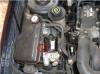
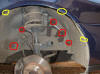
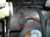
Looking at the picture below, this is how it looks before you take it all
apart and hopefully after you put it back together, the control box is under the
ABS pump which is just to the right of the expansion tank, circled in red is the
pump control connector, at this stage its very difficult to see where everything
is and space is quite tight. |
 |
| Start by removing the offside front wheel and the wheel arch
liner, the liner is held in place by 3 plastic screw clips (circled in yellow)
and 5 T30 screws (circled in red), note the you can just undo the forward clips
and screws then fold the liner out of the way. |
 |
| Once you’ve got the liner out of the way you need to undo the 3
½ inch nuts that hold the ABS pump / modulator assembly to the bottom of the
inner wing, mine were quite rusty so you will probably need some freeing oil and
some luck. |
 |
| It’s worth noting that Ford did not deem it necessary to topcoat
or protect the inner wing, I would guess it’s probably cheaper to use plastic
liners. You can quite plainly see here that undercoat has been applied but there
is a total lack of topcoat. |
 |
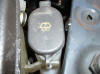
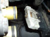
| You now need to remove the 10mm nut and 10mm self tapping screw
that hold in the expansion tank for the radiator, from the top of the inner
wing, be careful not to drop either of them as they will no doubt fall into the
most difficult place to reach! |
 |
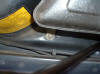
| You also need to remove the cap from the washer bottle, as you
can plainly see in the picture the expansion tank is slipped over a mounting lug
on the washer bottle. The cap just pulls off, try not to break the circular ring
that holds it on. |
 |
| Note that you do not need to disconnect the expansion tank as
there is just enough room to swing it over the top of the ABS pump and get it
out of the way. Remember to unplug the level sensor to give a bit more room. |
 |
| You now need to undo the 3 ½ inch ABS modulator / pump mounting
bolts 1 toward the rear of the car and 2 toward the front, the rear is easy to
get to, but the front inboard bolt is hard to reach, I found a 3/8 inch drive ½
inch socket did the trick, whereas a ½ inch drive was to large to fit in the
gap. |

 |
| Remove the mountings from the pump, they just pull off, note
that the lug on the mounting points upward and fits in the slot on the ABS
mounting bracket. |
 |
| Pull off the pipe that goes to the vacuum tank which is attached
to the ABS mounting bracket, don’t break the tube which sticks out of the tank
as the tanks are expensive. |
 |
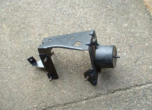
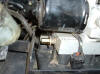
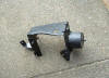
| It is now possible to remove the ABS mounting bracket complete
with the Vacuum tank, this picture is the underside of the bracket and shows the
vacuum tank still attached. |
 |
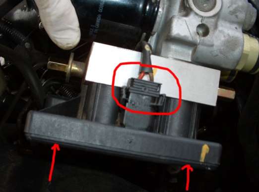
| At this point you are ready to disconnect the ABS modulator
control box, it is very important that the brake pedal is NOT pressed at this
point and that the ignition is not turned on inadvertently, there is a
possibility of serious injury if you don’t follow
these precautions. Disconnect the pump wiring (circled) by squeezing the tags
together and gently pulling upward, don’t pull on the cable and then unscrew the
2 T20 bolts from the bottom of the control box (arrowed). |
 |
| Pull the modulator control assembly downwards and swing it out
of the way, the bottom of the ABS pump should now look like this |
 |
| The six fingers pointing downward are the actuators for the ABS/TCS
system, don’t attempt to pull them out! If you look carefully you can see one of
the holes that the control box mounting screw fits into (to the top left of the
photograph), the other hole is directly opposite. |
 |
| Now you can disconnect the control wiring from the ABS computer
by unscrewing the 10mm bolt and pulling the connector off the control box, the
bolt comes out a long way so have some patience – nearly there now! You can
actually do this earlier but it is much easier to get to at this stage and
you’re less likely to break something. Withdraw the control box from the car.
Refitting is the reverse of dismantling but be careful not to over tighten the
T20 bolts that hold the control box and the 10mm bolt on the wiring connector,
Ford do not give torque settings for these bolts, but they are only screwed in
to about 20 foot lbs, road test the car and ensure GOOD braking performance
before you need it in an emergency.
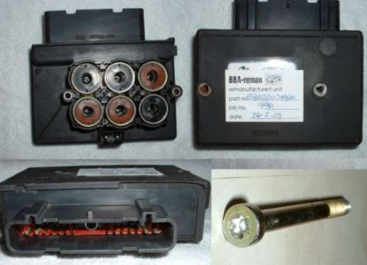
This is a photo of the Control Box and one of the T20 bolts that holds it to
the base of the ABS pump.
|
 |
Costings
1 remanufactured ABS modulator pump control box £366.00 inc VAT and
delivery, purchased from
BBA-Reman Ltd
9 Sabre Court
Gillingham Business Park
Kent
ME8 0RW
Tel 01634 230055
Web:
http://www.bba-reman.com/
BBA also do :- ECU’s, airflow meters, ABS controllers, pumps and modulators,
catalytic convertors, starter motors and alternators.
2 plastic trim clips from local Ford Main Dealer - 90p.
Time Taken - Approx 45 minutes
Workshop Manual
Download the following files by right-button click and save:
ABS Hydraulic Unit to 97
ABS Hydraulic Unit 97+
|
| |
|