*Diesel variants, two types of alternator may have been used,
changing 10/96.
Basic Alternator
It is not required to understand the following description for basic fault
finding.
The alternator, electrically consists of a few basic components. These are the
Rotor, Stator, Regulator and Diodes.
The Rotor is a coil of wire around an iron core. The Rotor rotates as the
alternator shaft rotates, current passes through brushes. The Rotor winding
passes the Field current. This causes the Rotor to produce a magnetic field. So
basically the Rotor is a rotating electro magnet.
The Stator is a set of three windings fixed to the case of the alternator, the
stator windings are static i.e. don’t rotate. As the Rotor rotates its magnetic
field “cuts” each Stator winding in turn, this induces a current in each
winding. The output from the Stator windings are 120 deg apart and are
alternating current, they swing nominally from +12V to -12V.
The Field current to the Rotor is provided by the Stator windings through
diodes. However when the engine is off and no Stator voltage exists, the Field current
is derived through the Warning Light, this provides a mechanism to start the
Alternator generating, when its not moving. (Sometimes called Pre Induction).
Diodes rectify the alternating 3 phases from the Stators and combine them into a
single Direct Current.
The Regulator controls the Field current flowing into the Rotor. If the systems
voltage increases the Field current is reduced, this causes a reduction in the
magnetic field of the Rotor and thus the final output voltage.

Warning Light
The Warning Light or Charge Light, is the one designated with a Battery symbol
and lights Red.
This is an LED, and provides an indication of faults within the charging system.
However the warning is not reliable under all conditions and failure modes.
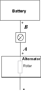
The best way to consider the operation of the Warning Light, is to view it as a
light with one connection to the battery + post and the other side to the
Alternator Output, in fact this is a slight simplification.

When the engine is not running and hence the Alternator is not rotating and
the ignition Key is to on, current flows from the battery + post through the
warning light, through the Rotor and out to ground (-). (In practice, depending
on the alternator design, the current also flows through internal electronics
then to ground). The Warning Light should be illuminated at this point, so
always check the illumination of the Warning Light when starting, i.e. with
engine off and key switched to on. The current flowing through the Rotor
provides enough Magnetic Field to start the Induction in the Stator. (This is
sometimes called Pre Induction). If this circuit, including the indicator LED, is
faulty no Pre Induction can take place.
When the engine is running and the Alternator is turning and working correctly
(providing sufficient current for the cars needs),
the output from the alternator at A is the same as the battery voltage at B,
hence no current flows through the Warning Light and the Light is off. (The
Alternator is sometimes said to be in Self Induction at this point when the
engine is turning)
If the alternator or battery either fails or its efficiency is reduced, a
difference in voltage would occur across A and B, and this will cause the Warning
Light to come on.
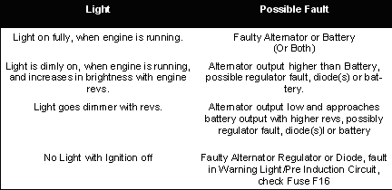
This can provide useful information on the health of the system. The following
table may help when fault finding the Scorpios charging system. Note the Warning
Light may not show subtle faults, also if the regulator or diodes are open
circuit the light will not illuminate.

Checking The Alternator & Battery
A common problem is how to distinguish between an Alternator or Battery
fault. Note its not uncommon for a Battery and an Alternator to both be faulty,
failing Alternators with Regulator faults can damage Battery capacities.
The Battery Discharges When Parked - Measuring Discharge Current
This procedure requires the reprogramming of various
systems including Radio Code, after the Battery is reconnected. Ensure you have
the Radio Code before proceeding.
If the electrical system appears to work ok when driving, but after parking the
car for some hours it has a discharged battery, the following test of Key Off
discharge current can be performed.
Various faults within the Scorpios electrical system can lead to a slow
discharge of the Battery when the ignition is off, to check for discharge
current. Measure the current flowing from the battery when the ignition is off
and all electrical equipment is turned off (as far as possible), waiting 1.5
hours after switching off will ensure power saving relay has shut down any
normal drain. To do this you will either require a DC non contact ammeter or a
Digital MultiMeter (DMM) with DC current range.
WARNING THE ENERGY STORED IN THE SCORPIOS BATTERY HAS THE POTENTIAL TO CAUSE
SEVERE BURNS AND EXPLOSIONS DO NOT SHORT CIRCUIT THE BATTERY.
With a DMM ensure its set to the highest current range and the leads are plugged
into the correct sockets for current measurement, also ensure the meter carries
either an internal fuse or has fused leads. If using a DMM the battery wire from
the + terminal should be removed, if two wires are fitted to the + post remove
both.
DO NOT ACCIDENTALLY ALLOW A SHORT FROM THE + TERMINAL TO
THE CARS METAL WORK.
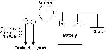
Measure the current flowing in from the battery to the cable(s) by connecting
the Negative (black) lead of the DMM to the Battery + (positive) terminal and
the Positive (red) lead to the cable that you just disconnected from the
Battery.

If the current flowing is over 80mA a problem exists with a discharge fault
someplace in the electrical system. This must be found and rectified. A faulty
Alternator short circuited Diode can also cause this problem. After factory
equipment, Car Cell phones, Alarms etc can often add excessive discharge
currents.
Battery Not Charging - Check For Bad Connections
Many faults with the Scorpios charging system can be caused by bad connections,
check all connections to the Battery and Alternator including all ground (earth)
connections which should have any corrosion removed from them.
Battery Not Charging - Testing The Battery
The best and surest way to check for a failing Battery is to totally remove it
from the charging system and charge it with an external battery charger. Charge
with the external charger following the charger manufacturers instructions,
noting all safety implications such as explosive gases and correct polarity. Once the Battery has been connected to the
charger for the recommended time remove it from the charger and have a “Dead
Short Test” performed. Most garages and Auto electricians can do this for you. This test
places a heavy electrical load directly across the battery, from this the Garage
or Auto electrician should be able to report the Batteries health. Any other
form of testing is not as conclusive and only a “Dead Short Test” is recommended.
NEVER PERFORM SUCH TESTS WITH THE BATTERY CONNECTED TO THE SCORPIOS ELECTRICAL
SYSTEM. SEVERE DAMAGE MAY RESULT.
Battery Not Charging - Testing The Alternator
If the Battery passes a “Dead Short Test” and is pronounced healthy and a charging fault exists, in many
cases the Alternator can safely be assumed to be faulty.
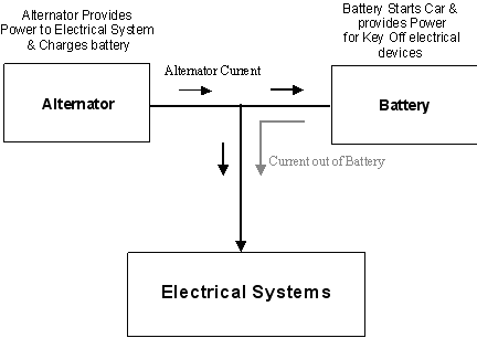
In fact the Alternator should be able to provide all the electrical current
required by the Scorpio even with a dead Battery once the engine is
running.
NEVER DISCONNECT THE BATTERY WITH THE ENGINE RUNNING AS SEVERE DAMAGE WILL
RESULT.
Even with a heavy electrical load i.e. Headlamps, heated screens, heated seats,
fans etc, once
the engine is running the Alternator should be able to provide sufficient current to power
these (and charge the battery at the same time). If the Battery is known to be good and with
prolonged electrical loading it is noticed that Headlamps dim or the fan slows
down etc, then the probable
cause is a faulty or failing Alternator that is not providing enough current. In this
condition the Battery begins to rapidly discharge as it provides the extra current to the
electrical system, in effect current flows out of the battery to power the load
but no current flows into the Battery to charge it.

In some cases it is feasible to have the alternator
repaired at an auto electrician but if the car has a high mileage this may be
false economy as other parts of the Alternator such as bushes or bearings will
be showing signs of wear. A new or reconditioned item is the best choice at such
times. A new Ford replacement for the 24V is approximately £250. An article
covering Alternator replacement is available here.

![]()
