Last update:

08/03/2005

  Sensor Test Values
About Us Useful Links Forums Mailing List
 

Up
Catalytic Converter
EEC-IV Code Reader
EECV PCM
EGR Systems
Engine Designs
Headlamp technology
WDS 2000
HT Circuit
Instrument Reset
Multiplex
Power and Efficiency
Power Steering
Sensor Test Values
Security - PATS
Synthetic Oils
VIS


 Sensor test values

IAT
The Intake Air Temperature sensor uses a reference voltage of 5V from the PCM.
The return voltage should be dependant upon the temperature of the inlet air and the resistance should be a direct inverse proportion to the temperature of the sensor. These are the test values:

Intake Air Temp C Resistance KOhms Voltage (V)
-40 880 4.53
-30 573 4.48
-20 272 4.33
-10 183 4.20
0 95 3.87
10 66 3.55
20 38 3.10
30 27 2.70
40 16 2.10
50 12 1.8
60 7.5 1.3
70 5.6 1.05
80 3.8 0.75
90 3.0 0.60
100 2.2 0.45
110 1.6 0.35
120 1.2 0.25

Note:
When the engine is cold, the resistance and output voltage from the Intake Air Temperature sensor should be the same as the resistance and output voltage of the Engine Coolant Temperature sensor (ECT) ie 35W and 3V respectively, depending on ambient temperature.

ECT
The return voltage should be dependant upon the temperature of the inlet air and the resistance should be a direct inverse proportion to the temperature of the sensor. These are the test values:

Resistance KOhms Voltage (V)
-40 880 4.53
-30 573 4.48
-20 272 4.33
-10 183 4.20
0 95 3.87
10 66 3.55
20 38 3.10
30 27 2.70
40 16 2.10
50 12 1.8
60 7.5 1.3
70 5.6 1.05
80 3.8 0.75
90 3.0 0.60
100 2.2 0.45
110 1.6 0.35
120 1.2 0.25

When the engine is cold, the resistance and output voltage from the Intake Air Temperature sensor should be the same as the resistance and output voltage of the Intake Air Temperature sensor (IAT) ie 35W and 3V respectively, depending on ambient temperature.

IPG
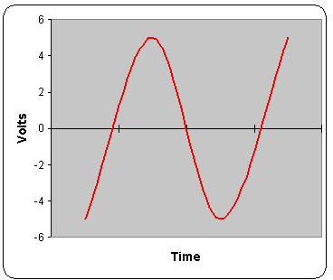
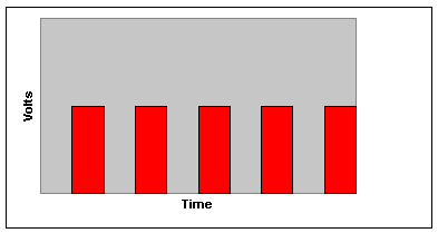
The Inductive Pulse Generator uses a permanent magnet situated close to a coil, between which passes an iron rotor which acts as a reluctor to the magnetic flux. As the reluctor passes between the magnet and the coil the change in flux produces a voltage in the coil which can vary from 0.5V to 100V, depending on the speed of the movement of the rotor. The signal is analogue, that is, in a sine wave varying from negative to positive value. Both the voltage and the frequency of the output signal varies according to the speed of the rotor, so both can be used for calculation.

Hall Effect
An advantage of the Hall generator is that it supplies a digital output, rather than the inductive pulse generator, which gives an analogue signal.

The Hall generator consists of a permanent magnet and a semiconductor chip separated by a vane driven in this case by the transmission gearing. As the vane rotates it passes the gap between the magnet and the chip, and the difference in magnetic flux causes the chip to switch on and off. A voltage is supplied to the chip and the return voltage consists of an on-off signal which will be timed to the rotation of the transmission. In this case the voltage of the signal does not vary, only the frequency.


Copyright © 2001 www.fordscorpio.co.uk