While all Scorpio radio installations included a radio
interface module, the lower specification radios did not include an amplifier.
This certainly included the 2001 radio unit, and probably the 2005 and 2015
radio/cassettes, because they are 2 speaker models only. Further, the highest
spec. models featured a Premium CD Sound system, which is dealt with last.
Let us begin with the circuitry for this lower spec without
amplifier.
Radio Less Amplifier
The installation includes the radio with connections C967a, and C967c,
the Radio Interface Module (RIM) C529, the radio remote control switch (RCS) (standard
after 1/95) C552 and the front and rear speakers connected directly to the
radio. If your radio includes an amplifier you will also see the connector C967d
on the radio.
The radio connectors are shown here:

Above, the C967a connector. Note that that there are two
options, higher and lower content options. I suggest that you will find that it
is the 7 pin connector on the right which you will find, particularly if you
have the Executive model.
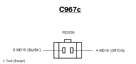
The C967c is shown above. It connects the radio to the RIM
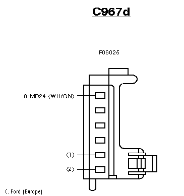
If a third connector is found, the C967d then you should be skipping this
part and going onto With Amplifier, because you got one!
There is no need to show the location of the radio - that
is obvious. But where is the Radio Interface Module? below is a view of the
connections behind the drivers lower fascia, the panel below the steering
column. It is easily removed by removing the visible screws and carefully
disconnecting the diagnostic multiplug. It is not necessary to detach the bonnet
release cable.

The RIM is the unit labelled as A101 and connector C529, which I show below.

It just remains to show the Remote Control Switch (RCS) connector C552
beneath the steering column shroud:

Now, since we know the connectors on the back of the radio, the location of
the RIM and the connectors on the units, we can begin to understand the
installation.
The RIM receives power through a 5A fuse No 8 in the Central Junction box to
Pin 10 on C529. Remaining connections are shown in the following table.
| Connector |
Colour |
Connector |
Purpose |
| CJB Fuse 8 |
Not shown |
RIM C529 Pin 10 |
Power supply to RIM |
| RIM C529 Pin 5 |
BK |
- |
Screening for Pins 4 and 13 to grnd |
| RIM C529 Pin 4 |
WH/VT |
Radio C967c pin not shown |
RIM to Radio before 2/95 |
| RIM C529 Pin 13 |
BN/WH |
Radio C967c pin not shown |
RIM to Radio before 2/95 |
| RIM C529 Pin 4 |
GY/OG |
Radio C967c pin not shown |
RIM to Radio 2/95 on |
| RIM C529 Pin 13 |
BU/BK |
Radio C967c pin not shown |
RIM to Radio 2/95 on |
| RIM C529 Pin 14 |
BU/OG BU/RD |
Radio C967a Pin 7 |
RIM to radio |
| RIM C529 Pin 16 |
BK |
To Ground |
Ground for RIM |
| RIM C529 Pin 8 |
BK/RD |
RCS C552 Pin 3 |
Signal fm RCS, volume down |
| RIM C529 Pin 15 |
BK/RD |
RCS C552 Pin 4 |
Signal fm RCS, volume up |
| RIM C529 Pin 2 |
BK/RD |
RCS C552 Pin 1 |
Signal fm RCS, seek up |
| RIM C529 Pin 11 |
BK/RD |
RCS C552 Pin 2 |
Signal fm RCS, seek down |
| RIM C529 Pin 12 |
BK/RD |
RCS C552 Pin 6 |
Signal fm RCS, tape/disk/autochange |
| RIM C529 Pin 9 |
BK |
RCS C552 Pin 7 |
Ground for signal fm RCS, |
| CJB Fuse 8 |
Not shown |
Radio C967a Pin 3 |
Power for Radio |
| CJB Fuse 1 |
Not shown |
Radio C967a Pin 1 |
Power for Radio |
| Radio C967a Pin 2 |
Not shown |
Ground |
Ground for radio |
| Radio C967a Pin 6 |
Not shown |
Ground |
Ground for radio |
| Radio C967a Pin 5 |
BK/OG |
CCM C494a |
Connection for Central Control Module |
| Radio C967e Pin 3 |
WH/VT |
L Rear Speaker |
Connection for Left Rear Speaker |
| Radio C967e Pin 4 |
BN/WH |
L Rear Speaker |
Connection for Left Rear Speaker |
| Radio C967e Pin 7 |
WH |
R Rear Speaker |
Connection for Rt Rear Speaker |
| Radio C967e Pin 8 |
BN |
R Rear Speaker |
Connection for Rt Rear Speaker |
| C467 Light switch Pin 3 |
GN/BK |
Radio C967a Pin 4 |
Lighting on for radio before 2/95 |
| C467 Light switch Pin 14 |
OG/BK |
Radio C967a Pin 4 |
Lighting on for radio 2/95 On |
| Radio C967e Pin 1 |
WH/BK |
L Front Speaker |
Connection for L Front Speaker |
| Radio C967e Pin 2 |
BN/YE |
L Front Speaker |
Connection for L Front Speaker |
| Radio C967e Pin 5 |
WH/RD |
R Front Speaker |
Connection for Rt Front Speaker |
| Radio C967e Pin 6 |
BN/RD |
R Front Speaker |
Connection for Rt Front Speaker |
You'll note that there is no connection for the Vehicle Speed Sensor in this
installation. This signal is used for the Auto Volume Control on higher spec
models, and is useful for SatNav installations. Also useful is the detail of the
internal connections for the Remote Control Switch (RCS) If you need to connect
a different head unit it may be possible to make up your own connections for it.
Next, the installation with the Amplifier.
Radio With Amplifier
As you would expect, the amplifier intercepts the speaker signals from
the radio, so the speakers are not connected to the radio at all - this has
caused some confusion. Hopefully it will become clearer now.
First, we need to locate the amplifier A13.
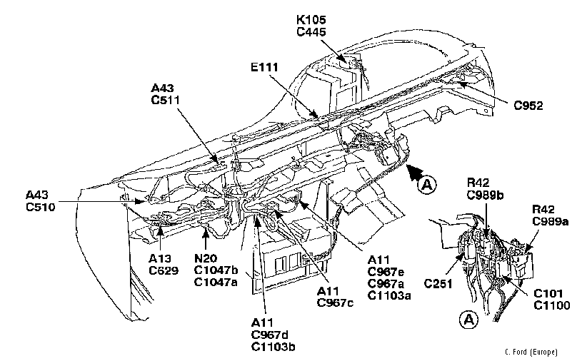
The Amplifier A13 is behind the glove box, reached by pushing the glove box
stays outward lowering the glove box and removing the lower passenger side
fascia. It is connected by C629, shown next:
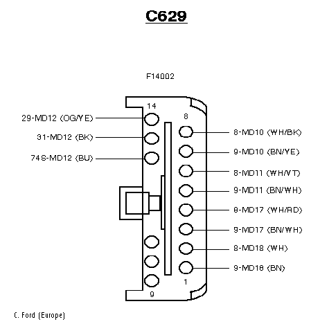
However, there is a complication. Apart from the speaker outputs and a few
others on C629, all connections between the radio and the amplifier are simply
shown as Ca and Cc. Pins 1 to 8 on the radio are shown connected
to pins 8 to 1 on the amp, but the functions of the wires are not shown. I
believe this to be a cable connector, using round din-type multiplugs at both
ends.
This need not be a problem. If one is installing a new head unit you wouldn't
need to use the amplifier at all, and the power to it can be disconnected. If
you are fitting only an amplifier - then there's a problem. Ultimately all that
can be done is use the speaker out connections - unless you can test the pins on
the amplifier end of the cable connector and find the low-level amp input.
The pins for the Remote Control Unit (RCU) and the Radio Interface Module
(RIM) remain the same except that C967c is replaced with C967d.

Connector detail is as follows.
| Connector |
Colour |
Connector |
Purpose |
| CJB Fuse 8 |
Not shown |
RIM C529 Pin 10 |
Power supply to RIM |
| RIM C529 Pin 5 |
BK |
- |
Screening for Pins 4 and 13 to grnd |
| RIM C529 Pin 4 |
WH/VT |
Radio C967d pin not shown |
RIM to Radio before 2/95 |
| RIM C529 Pin 13 |
BU/BK |
Radio C967d pin not shown |
RIM to Radio before 2/95 |
| RIM C529 Pin 4 |
GY/OG |
Radio C967d pin not shown |
RIM to Radio 2/95 on |
| RIM C529 Pin 13 |
BU/BK |
Radio C967d pin not shown |
RIM to Radio 2/95 on |
| RIM C529 Pin 14 |
BU/WH |
Radio C967d Pin 7 |
RIM to radio |
| RIM C529 Pin 16 |
BK |
To Ground |
Ground for RIM |
| RIM C529 Pin 8 |
BK/RD |
RCS C552 Pin 3 |
Signal fm RCS, volume down |
| RIM C529 Pin 15 |
BK/RD |
RCS C552 Pin 4 |
Signal fm RCS, volume up |
| RIM C529 Pin 2 |
BK/RD |
RCS C552 Pin 1 |
Signal fm RCS, seek up |
| RIM C529 Pin 11 |
BK/RD |
RCS C552 Pin 2 |
Signal fm RCS, seek down |
| RIM C529 Pin 12 |
BK/RD |
RCS C552 Pin 6 |
Signal fm RCS, tape/disk/autochange |
| RIM C529 Pin 9 |
BK |
RCS C552 Pin 7 |
Ground for signal fm RCS, |
| RIM C529 Pin 16 |
BK |
Ground |
Ground for RIM |
| CJB Fuse 8 |
Not shown |
Radio C967a Pin 3 |
Power to Radio |
| CJB Fuse 1 |
Not shown |
Radio C967a Pin 1 |
Power to radio |
| CCM C494a Pin 10 |
BK/OG |
Radio C967a Pin 5 |
Timer signal from CCM |
| Radio C967d |
WH/GN |
Vehicle speed sensor |
Speed pulse signal for radio |
| Radio C967a Pin 2 |
Not shown |
Ground |
Ground for radio |
| Radio C967a Pin 6 |
Not shown |
Ground |
Ground for radio |
| Radio C967a Pin 8 |
BU |
AMP C629 Pin 12 |
Radio to Amp |
| CJB Fuse 1 |
Not shown |
AMP C629 Pin 14 |
Power to Amp |
| AMP C629 Pin 13 |
Not shown |
Ground |
Ground for Amp |
| AMP C629 Pin 8 |
WH/BK |
L Front speaker |
L Front speaker |
| AMP C629 Pin 7 |
BN/YE |
L Front speaker |
L Front speaker |
| AMP C629 Pin 4 |
WH/RD |
R front speaker |
R Front speaker |
| AMP C629 Pin 3 |
BN/RD |
R Front Speaker |
R Front speaker |
| AMP C629 Pin 2 |
WH |
R Rear speaker |
R rear speaker |
| AMP C629 Pin 1 |
BN |
R Rear speaker |
R rear speaker |
| AMP C629 Pin 6 |
WHVT |
L Rear speaker |
L rear speaker |
| AMP C629 Pin 5 |
BN/WH |
L Rear speaker |
L rear speaker |
| C467 Light switch Pin 3 |
GN/BK |
Radio C967a Pin 4 |
Lighting on for radio before 2/95 |
| C467 Light switch Pin 14 |
OG/BK |
Radio C967a Pin 4 |
Lighting on for radio 2/95 On |
| Radio Ca Pins 1 to 8 |
- |
Cc Pins 8 to1 on Amp |
Believed DIN style cable |
| |
|
|
|
There now remains the Premium Sound System installation.
Premium Sound System
Standard equipment for the Ultima and available as a cost option for others,
is the Premium Sound System. This adds a CD autochanger (CDC), mounted in the
boot of the saloon or behind the nearside rear luggage trim on the estate. The
connector for this is C565.
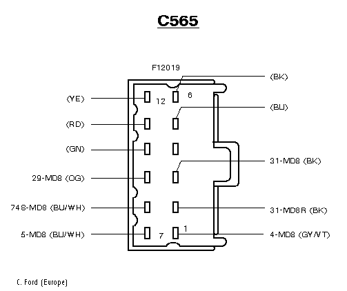
Otherwise the installation follows the standard practice in the
Scorpio. The connections for the CD changer (CDC) are spliced into the
connections between the Radio and the RIM. Because the wires from pins 1 and 7
on the CDC are shielded by a grounding pin it would appear that these carry the
low level signals.
| Connector |
Colour |
Connector |
Purpose |
| CJB Fuse 8 |
Not shown |
RIM C529 Pin 10 |
Power supply to RIM |
| RIM C529 Pin 8 |
BK/RD |
RCS C552 Pin 3 |
Signal fm RCS, volume down |
| RIM C529 Pin 15 |
BK/RD |
RCS C552 Pin 4 |
Signal fm RCS, volume up |
| RIM C529 Pin 2 |
BK/RD |
RCS C552 Pin 1 |
Signal fm RCS, seek up |
| RIM C529 Pin 11 |
BK/RD |
RCS C552 Pin 2 |
Signal fm RCS, seek down |
| RIM C529 Pin 12 |
BK/RD |
RCS C552 Pin 6 |
Signal fm RCS, tape/disk/autochange |
| RIM C529 Pin 9 |
BK |
RCS C552 Pin 7 |
Ground for signal fm RCS, |
| RIM C529 Pin 16 |
BK |
Ground |
Ground for RIM |
| PJB Fuse 1 |
Not shown |
C967a Pin 1 |
Power for Radio |
| Radio C967a Pin 2 |
Not shown |
Ground |
Ground for Radio |
| Radio C967a Pin 6 |
Not shown |
Ground |
Ground for Radio |
| Radio C967a Pin 4 |
GN/BK |
To light switch |
Lights on for radio |
| Radio C967a Pin 7 |
BU/WH |
CDC C565 Pin 8 |
Radio to CDC |
| As above fm BU/WH |
BU/OG |
RIM C529 Pin 14 |
CDC to RIM |
| Radio C967d |
GY/OG or WH/VT |
RIM C529 Pin 4 |
Radio to PIM (shielded) |
| as above from GY/OG |
GY/VT |
CDC C565 Pin 1 |
Radio & PIM to CDC |
| Radio C967d |
BU/BK or BN/WH |
RIM C529 Pin 13 |
Radio to PIM (shielded) |
| as above from BU/BK |
BU/WH |
CDC C565 Pin 7 |
Radio &PIM to CDC |
| CDC C565 Pin 2 |
BK |
Ground |
Ground for CDC |
| RIM C529 Pin 5 |
BK |
Ground |
Grnd for Pins 1 & 7 on PIM |
| Radio C967d Pin 6 |
WH/GN |
VSS |
Speed signal for radio |
| Radio C967a Pin 8 |
BU |
RIM C529 Pin12 |
Radio to RIM |
| Radio C967a Pin 5 |
BK/OG |
Anti Theft Alarm |
Signal for Alarm |
| AMP C629 Pin 13 |
Not shown |
Ground |
Ground for RIM |
| AMP C629 Pin 8 |
WH/BK |
L front speaker |
L Front speaker |
| AMP C629 Pin 7 |
BN/YE |
L front speaker |
L Front speaker |
| AMP C629 Pin 4 |
WH/RD |
R front speaker |
R Front speaker |
| AMP C629 Pin 3 |
BN/RD |
R front speaker |
R Front speaker |
| AMP C629 Pin 14 |
Not shown |
CJB Fuse 1 |
Power for AMP |
| AMP C629 Pin 6 |
WH/VT |
L Rear Speaker |
L Rear Speaker |
| AMP C629 Pin 5 |
BN/WH |
L Rear Speaker |
L Rear Speaker |
| AMP C629 Pin 2 |
WH |
R Rear Speaker |
R Rear Speaker |
| AMP C629 Pin 1 |
BN |
R Rear Speaker |
R Rear Speaker |
| Radio Ca Pins 1 to 8 |
- |
Cc Pins 8 to1 on Amp |
Believed DIN style cable |
| |
|
|
|
That's the radio installation for the Scorpio to 9/95. I hope this will be
useful for anyone contemplating upgrading their stereo. For myself, I have the
Estate with the Premier Sound System, and I see that Ford did not bother with
good speakers in the rear - probably too far away. I upgraded mine with a
separate amp using hi-level input from the rear speakers, and replaced the fibre
things with Pioneer 6 X 9s. Oh, and a Pioneer sub. See Hi Fi
for details.

