|
|
|
|
|
Last update: 05/26/2006 |
|
|
|
|
|
|
|
|
|
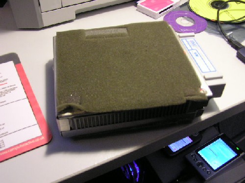
PCM Repair Darren, (Sector-9 on the Forum) has sent us details of the repair he carried out on the PCM (Powertrain Control Module) on his 2.5 TDi. Let him tell his own story ... Today I finally got my EGR valve working. Initially it looked like a faulty solenoid valve as the multi-meter showed 12V between the terminals. However, putting any kind of load on the terminals dropped the voltage down to zero! Because I've had problems with the loom previously I thought it might be this so I cut the two wires for the EGR valve close to the ECU behind the glove-box. I then connected a test lamp to the wires from the ECU. The theory being that if the loom is faulty then the test lamp will light when the solenoid should have been operating. Imagine my despair when the lamp connected directly to the ECU didn't do anything. Moreover, it showed exactly the same problem as at the solenoid itself - 12V between the wires until any load is applied. Further tests showed that the positive output from the ECU was working fine (lamp lit okay when earthed to body), but the negative connection was bad. This could only mean one thing (well two actually, but I'd already checked the earth connection to the ECU) - the ECU had to be faulty! Well I could have asked somebody on here if they had a spare, or I could have paid £40+ for one from a scrapyard (assuming any nearby had one which is doubtful), but I decided to have a go myself. Okay, first thing is to remove the ECU from the car. This is relatively easy and the glove-box and ECU both come out without any tools. Unfortunately you do need a 10mm socket to unscrew the loom multi-plug from the ECU but what you end up with is this:
Next thing to do is remove the casing, which is two screws on the top, two on the bottom (both near the connector and hidden under the foam) and one holding a blanking plate on the end. At this point I need to warn about the dangers of static electricity and the damage it can do to electronics so make sure you've earthed yourself! Now that the ECU is laid bare I could get the multi-meter out. I already knew that the negative side of the EGR solenoid connects to pin 43 of the ECU so it's simply a matter of using the meter set to continuity test to find what pin 43 connects to internally. Actually it's not that simple - the PCB has been coated with lacquer after assembly and this needs to be scraped off at the joint to be tested, otherwise it acts as an insulator and you don't get any readings. It's also made harder by the fact it is a double-sided PCB which makes it harder to visually follow the tracks as they frequently swap sides! A strong lamp shining through from the back of the PCB helps a little and you can tell from the little solder links when it changes side. Now to save me testing for continuity between every joint on the board and pin 43 it's time to apply some common sense. Firstly, we know from the Ford TSB that the solenoid has a resistance of 6 ohms, which at 12V means it draws a current of 2 amps (amps=voltage/resistance). 2 amps is quite a bit of power as far as electronics goes so it's going to involve some big, meaty components. Also that amount of power will generate a fair bit of heat. So what we're looking for is a fairly large component that's mounted so as to keep cool. Basically we're looking for large power-transistors or similar. The other clue is that there is 12V between the two wires to the solenoid until a load is put across them. That means that there is a resistance in the circuit since the full voltage will be present across an open circuit, but dropped by a specific amount when the circuit is completed (resistors in series). The fact it was being dropped down to zero means that there was a very high resistance somewhere in the negative side of the circuit. With the lid off I can see that there are four large transistor type devices attached to the metal casing to dissipate heat. It's just a matter of checking for continuity between pin 43 and the terminals of each device. Unfortunately in this case there wasn't continuity between pin 43 and any of them (though there was between pins 42 and 41 to two of them). Typing in the model number on the front of each into Google revealed that the two devices connected to pins 41 and 42 respectively were solid-state relays, whilst the third on the same side of the PCB was a 5V regulator. The single device on the opposite side had no markings so I've no idea what it's for. The next thing is to check for continuity between pin 43 and the big resistors which have been stood off the PCB (to help keep them cool). Bingo! One side of resistor R4 connects directly to pin 43. Measuring the resistance across R4 it appears to be about 9600 ohms which using the above formula would allow through about 1 milliamp - not enough to do anything. This very high resistance is the cause of the volt drop down to zero when any load is put in the circuit. The other give away is that R4 is blackened and visibly burnt out (though I didn't realise it shouldn't have been that colour!).
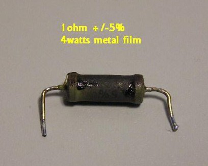
I must confess my actual electronics knowledge isn't that great so it's time to get help with this one. I took it to our local computer club because one of the members is a TV/video repair guy. He looked at it and agreed that R4 should have much lower resistance if it's going to pass 2 amps through it (he also says it shouldn't be that yucky black/brown colour!). After unsoldering it from the PCB we read the remainder of the markings underneath which indicated that it is a 1 ohm resistor. Unfortunately we did not know what power rating it is but the equation watts = current2 * resistance gives us 22 (4) * 1 (still 4) = minimum rating of 4 watts. He also advised not to use wire-wound resistors as these will glow red hot if overloaded, possibly melting the PCB! Okay, so I now definitely knew what and where the fault was on the ECU. Time to go to Maplin and buy a replacement resistor. Unfortunately the only resistors they do at 1 ohm is a wire-wound type! Oh well, nothing for it - I bought a 7 watt, 1 ohm wire-wound resistor and glued it onto the metal framework of the ECU to help keep it cool and so that it's not near the PCB if it does overheat. The leads from the resistor didn't reach the solder terminals for R4 on the PCB so I had to solder a short length of wire to each side of the new resistor and insulate. The wires were then soldered into the holes previously occupied by R4. This is a photo of the ecu with the lid removed and the replacement resistor fitted: and here is the underside showing the new resistor itself and where it is mounted
You'll notice I've also labelled up a few other key components I've identified within the ECU! With the lid fitted and ECU connected back up the EGR solenoid is now working fine. I know it all sounds really complicated but finding the fault didn't actually take that long. Fixing it only took 15 minutes and cost about 25p for the new resistor. Congratulations if you read all of the above and understood it - even if you don't feel confident tackling it yourself, a TV repair person could probably quite easily track down and fix many ECU problems as the chips and stuff are unlikely to be the cause. Just goes to show that things considered "off limits", even for mechanics aren't necessarily irreparable! Final piccy showing the label on the ECU:
When I get chance I'll post my guesses on what the ECU actually controls and how. Thanks to Darren for pix and text. |
|||
|
|
|
Copyright © 2006 www.fordscorpio.co.uk |
|