2.5 TDI Diesel to 9/96 (All Manual)
The TDI model was with manual transmission only until
9/96, when an automatic was announced. In the intervening period the Powertrain
Control Module (PCM) changed, and some engine controls between 3/96 and 9/96
were revised.
Circuit Description (before 03/96)
Cold Start System
Ignition On
With the ignition switch (N278) in position 2 (run), the diesel pre-glow relay
(K70) receives voltage. The pre-glow warning light in the instrument cluster
(A30) illuminates and the glow plugs (P20) receive voltage. The warning light
remains on until the pre-glow period is over.
Starting the Engine
While the engine is being started (ignition switch (N278) in position 3
(start)), the glow plugs (P20) continue to receive current from the diesel
pre-glow relay (K70).
Engine Running
During the engine warm-up period, the glow plugs (P20) continue to receive
current until a certain engine temperature is reached.
Powertrain Control Module (PCM)
The powertrain control module (PCM) (A147) has been programmed specifically for
various engine types. The module stores all information necessary to ensure
precise exhaust gas recirculation. Based on input signals from various sensors,
the actual values are compared to the stored desired values and if necessary,
control or adjust signals are sent to the respective components.
Injection Control
The diesel cold advance valve solenoid (Y83) adjusts the injection timing to
"early" with help from the injector valve (Y63). The injection timing must be
adjusted to achieve optimal combustion under various load and rpm conditions.
A needle motion sensor in the injector valve (Y63) adjusts the injection timing
to "early". After the engine has reached its operating temperature, the diesel
cold advance valve solenoid (Y83) is turned off.
Exhaust Gas Recirculation (EGR)
The Exhaust Gas Recirculation (EGR) system is controlled by the EGR solenoid
valve (vacuum) (Y49) which is connected to pins 42 and 43 of the PCM (A147). The
EGR solenoid valve (Y49) opens a bypass between the exhaust and intake
manifolds. Additional signals to the PCM (A147) from the engine speed sensor
(B7), the Engine Coolant Temperature (ECT) sensor (B10) and the Throttle
Position Sensor (TPS) (B8) also influence the EGR system.
Sensors
The Fuel Lever Variable Resistor (FLVR) sensor (B98) is a potentiometer which
sends a signal of the fuel lever position to pin 51 of the PCM (A147). Using
this information, the PCM (A147) calculates fuel delivery depending on the
engine load (idle, partial load, wide open). The Fuel Lever Variable Resistor
(FLVR) sensor (B98) receives a 5 V reference voltage from pin 50 and is earthed
at pin 52 of the PCM (A147).
The engine speed sensor (B7), an inductive pulse generator, sends an alternating
voltage signal to the PCM (A147). The signal serves as information about the
engine rpm and is used in determining the injection timing. The engine speed
sensor (B7) is connected to pins 54 and 55 of the PCM (A147).
The Engine Coolant Temperature (ECT) sensor (B10), a temperature-dependent
resistor, is connected to pins 53 and 58 of the PCM (A147). The ECT sensor (B10)
provides the PCM (A147) with the engine temperature, which is then used to
calculate the corresponding cold start adjustment, the amount of exhaust gas
necessary for exhaust gas recirculation and, at high temperatures, air
conditioning cut-off.
Diagnostic and Ground Connections
Pins 27 and 45 of the PCM (A147) lead to pins 3 and 11 of the Data Link
Connector (DLC) (D20).
Pins 40 and 60 of the PCM (A147) are connected to the negative battery terminal
(ground). Pin 20 of the PCM (A147) is connected to ground G7 via splice S77.
Fuel Heater
The fuel heater (R32) warms the diesel fuel to prevent a paraffin separation at
cold temperatures. The heating element consists of a ceramic resistor whose
resistance increases with increasing temperature. The resistor is protected from
overheating by an integrated thermoswitch and reaches a maximum temperature of
130 °C.
Connections.
The following tables are for the 2.5 TDI produced between
10/94 and 9/96. They should not be used for later models where there was a
change of PCM and a completely different loom was introduced.
Additional changes in engine controls between 3/96 and
9/96 are concerned with the wiring to the fuel shut-off valve and fuel heater
and do not effect the wiring for the PCM.
The PCM multiplug, C464, is unique to this model. The
location of the PCM is still behind the glovebox under the dash and is reached
in the same way as the petrol models.

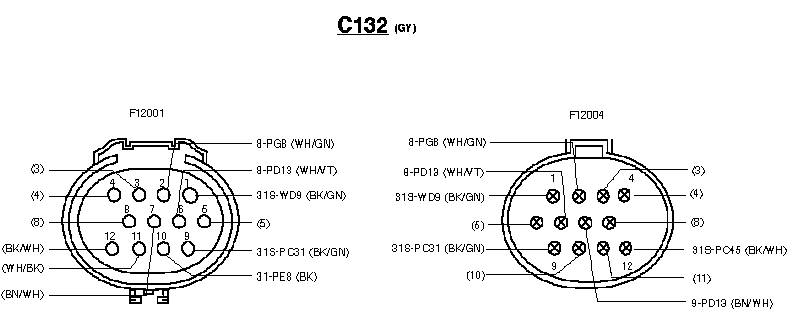
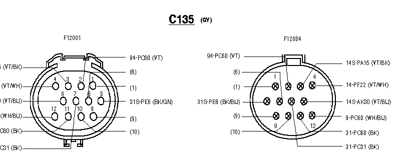
The engine connections are C132 and C135. They are also of
a completely different design to petrol models, but are in the same location -
on the driver's side engine bulkhead. Note - LHD model shown.

You will note that although the connections have identical numbering the
wiring colours are different.


Engine Connections thru Engine Loom.

