|


|
|
Audible Alert on
Lock and Unlock
The Scorpio comes with two variations of Central Locking. The lower specified
system utilises traditional direct methods. The higher specified system uses
“Global Closing”. This system uses a bus topology to control the locking system
and other features such as power windows, sunroof and seating.
On the Global Closing variation, the locking can be deadlocked by a second
operation of the Key Fob Remote or actuation of the Key Lock; this also arms the
Ultrasonic Interior Alarm Sensors when fitted. After arming in this way, the
system flashes the indicators within a few seconds to acknowledge that the alarm
has adjusted to the cabin and has armed. This may not apply to all vehicles as
this behaviour is modified between markets.
However neither system provides an audible indication that the locks have
operated. The mechanical noise from the locks is low and I found it difficult to
fully be sure the car was locked without actually visually checking, or
deadlocking the car and waiting for the indicators to flash. So it was decided
to add some method of audible feedback.
Possible Methods
With the traditional system, adding a system to detect locking would be
straight forward, however I have the Global Closing system. One option would be
to actually get at a lock motor and break into its feed, however this is
complicated by the fact that this would have to be done inside the door skin, as
the feed to the locks is shared with other modules within the door. More
sophisticated, would be to monitor the bus, decode the signals and initiate a
signal this way. However this was going to be reasonably time consuming, and
would involve interfacing to the bus. I felt that it would be preferable to keep
the system to original specifications.
The third method considered, was monitoring the current flowing to the locking
system, this was the method chosen. The system is passive in its connection to
the locking system and should work on any Scorpio.
Design
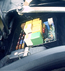
It was decided that the system should be easy to fit into the car, i.e. no
major wiring or removal of components. From this the design developed, of a plug
in circuit, which sat in the Main Fuse Box.
 |
 |
A printed circuit board was designed for the system, this fits into the fuse
box, Fuses 22 and 21 are removed and the board piggybacks into the fuse holders
in the fuse box. Fuse 22 is the locking system fuse and Fuse 21 the heated
mirror fuse.
The operation of the circuit is as follows. When the locking motors are
activated the current flowing through the circuit that Fuse 22 protects
increases considerably, than the level at standby. An isolated Current
Transducer, CT1 is used to measure this current. CT1 provides an analogue output
dependent on load current. This signal is fed to a small microcontroler that has
an internal analogue to digital converter built in. From this the microcontroler
decides if the locking motors are activated. Additionally the way that the
Heated Mirror circuit within the Scorpio is designed, no voltage appears on Fuse
21 the mirror fuse, until the Heated Rear Screen Switch is activated. This gives
a method of signalling the system if required. If the system decides that the
locks have been operated, it produces a 4.5Khz signal that is sent to a piezo
transducer, also an auxiliary output is switched on and off. The auxiliary can
be used to drive an external relay, as to provide indication through the horn or
headlamps if required.
width="100" height="141">
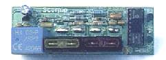
Construction
Some experience with soldering is required to construct this project, that
said it should be reasonably straightforward. The p.c.b. is a double sided
through hole component, with silkscreen and solder resist, this makes assembly
easier. The silk screen shows component identifications, these correspond with
the schematic. It is recommended that the resistors are fitted first, followed
by diodes, capacitors, transistors, resonator, IC socket and voltage regulator.
Lastly the fuse holders and then, the following connector details.
PARTS LIST
| Scorpio Audio Locking Alert |
| Quantity |
Description |
Vendor |
Part No. |
| 1 |
Piezo awd 100dB @ 4.5KHz |
Farnell |
926-991 |
| 1 |
Current Trans LEM |
Farnell |
394-3501 |
| 2 |
Fuse Holders |
Farnell |
581-525 |
| 1 |
PCB Fuse 125mA* |
Farnell |
319-260 |
| 1 |
PIC16C71 |
Farnell |
270-386 eprom/ 270-398 otp |
| 1 |
4mHz Resonator* |
Farnell |
573-589 |
| 1 |
78L05 Vreg |
Farnell |
701-889 |
| 1 |
Transistor PDTC124 (Resistor equipped) |
Farnell |
316-4494 |
| 3 |
All 5% 0.25W Resistor 2K * |
|
|
| 1 |
Resistor 11K* |
|
|
| 1 |
Resistor 22K* |
|
|
| 1 |
Resistor 15K* |
|
|
| 1 |
15V Zenner* |
Farnell |
369-512 |
| 1 |
5.1V Zenner* |
Farnell |
369-408 |
| 3 |
100nF Capacitor* |
Farnell |
750-992 |
| 2 |
22pF Capacitor* |
Farnell |
747-038 |
| 1 |
100uF 6.3V Capacitor* |
Farnell |
301-7527 |
| 4 |
PCB small faston conn for gnd and piezo* |
Farnell |
347-2528 |
| 1 |
18 Pin DIL Socket* |
Farnell |
134-2990 |
I used Farnell
Electronics for the parts. Some components are only sold in multipacks by
Farnell, Maplin Electronics etc can supply some components listed in smaller
quantities but the Current Transducer and Resistor
Equipped Transistors may be difficult to source elsewhere.
Power Connection Manufacture.
Assembly is straight forward, however the most time consuming part is
constructing connections to plug into the existing fuse holders, in the Scorpios
Main Fuse Box.
Large currents can flow in these circuits, so care must be exercised.
The specified PCB mounting fuse holders are rated at a continuous current of
15A, this becomes a possible problem as the door locking circuit is protected by
a 20A fuse. In tests nothing like that current is used by the locking motors. In
extreme conditions, mechanically jamming locks or frozen up locks, these
currents possibly could flow for a brief period. The specified fuse holder will
handle this for some time. If in doubt use a 15A fuse in place of the 20A, if
you have no problems with it blowing.
The connections to the power circuits, i.e. fuse 22 and 21 must be suitably
constructed, as so to handle these currents. The method I chose is shown in the
following pictures. I originally was going to have connections CNC’d and
tin-plated, however time did not allow. I think some one else can come up with a
better method. One list member at least is looking at this.
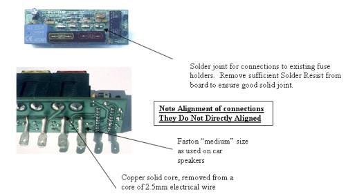
Use faston spade connectors of the medium general size as used on car radio
speakers, available from Motor World/Halfords etc. They come with a plastic
sleeve, the colour of which identifies the designed cable diameter and current
rating. Use ones with a red sleeve. Strip some 2.5mm electrical wire (twin and
earth) and prepare a striped core, by cleaning it until bright, use a needle
file etc, never wire wool as it contains oils.
The PCB has slits, so designed for a CNC’d assembly, they do not centre with the
fuse holders as they are. Refer to the picture above. Remove sufficient solder
resist from the top of the board around the area to be soldered to. Once you are
sure about the alignment, if necessary open the slits at the required positions
slightly, I used a few turns of a round needle file. Solder in 4 lengths of
about 25mm, you need a soldering iron that can do at least 30W if you want good
results. Ensure the joint is sound, inspect carefully. You do need some
experience with soldering to do this correctly.
Once cooled down place a faston spade, with its outer sleeve in place, over the
wire on the solder side of the board. Very carefully solder the crimp to the
wire, you need to provide the heat for at least 8 seconds until capillary action
draws sufficient solder into the crimp. The crimp needs to be filled with
solder. Carefully, mind your fingers, before the crimp has cooled completely;
use a pair of pliers to pull the still malleable sleeve up and off. Leaving the
sleeve in place until this point, levels the connection at the correct height.
Repeat until all four connections are in place.
The use of copper wire provides some “adjustment” if your alignment is slightly
out.
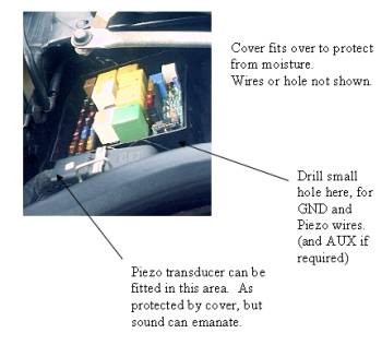
Low Power
The low power connections consist of, GND, outputs to the piezo and AUX.
Thin wire can be used here, the board has provision to mount small faston
connectors for these connections, or solder the wires directly into the board.
The specified transducer can provide considerable noise output. For best results
place a 1K 0.25W resistor in parallel with it, near to its leads.
Software
I used a Microchip PIC16C71, microcontroler. This device comes in two basic
flavours, the one time programmable or otp and the EPROM type. Other devices
could be used including possibly AVR products from Amtel.
The original software is very basic and does not make use of all the possible
features. I used a C compiler for speed and the relevant source code and hex
files are included in awd.zip, so you can program your own
devices if you have access to the facilities.
Click here to download awd.zip
RB1 can be used to detect when rear screen heater is pressed, could use
combination of pushes on this to enter program mode etc. (not done this
yet, in software).
RA0 can be used to monitor battery voltage, this again has not been implemented
in code. But all the hardware is on the board.
Printed Circuit Boards and Programmed PIC16C71
A limited number of pcbs are available, as a reasonable batch had to be
manufactured for minimum quantity reasons. These are available to interested
Scorpio owners.
The PIC16C71 is available ready programmed with the basic original software.
Disclaimer and Legal
No warranties or guaranties are given; no responsibility for damage is
taken, for use of this design. It is provided purely for diy use and you are
responsible for its use and integration. All details, source code etc can be
freely used and modified for non-commercial purposes.
|
|
