Installation
The module is quite simple to fit, but required about 3 hours in total.
Access to the wires behind the nearside front side wall and beneath the steering
wheel is needed for connection.
Tools Required:
T25 Torx bit
Cross head screwdriver
Torch or lighting
Electrical terminals
Soldering iron or Scotchlok connectors
Circuit tester or multimeter.
Connections to PCB
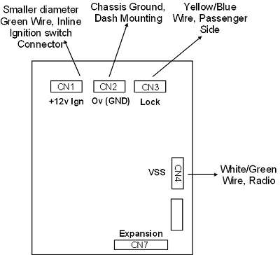
All connections to the PCB are made with faston push on connectors. Ensure the
+12V cable to CN1 and the Lock connection CN3 is suitably rated and can pass 15A
without over heating.
CN1 is the +12V supply; this can be connected to the Key On (Position 2)
ignition switch wire. The driver’s dash area that contains the Coin Box can be
dissembled by removing 5 screws. Two T25 from the side and two from inside the
Coin Box and one on the left underneath. The Trip Computer connection is
unclipped, and the large OBD connector is prised out of the housing be levering
the bottom raised edge. The bonnet release cable can be left in place. Locate
the wires from the ignition switch and follow down to an inline connector in the
centre of the shelf.
The smaller diameter green wire can be connected to using a scotch lock or
similar.
CN2 is 0V (Chassis Ground), the screw that mounts the Wood Effect dash area at
the top of the drivers side lower dash area can be easily utilised as a Ground,
use a suitable circular crimp lug. Another useful very good earth is the Airbag
Module mounting, another T25screw. This id directly above the shelf.
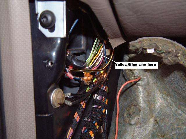
CN3 is the connection to the Central Locking Lock signal, it is easy to locate
on the front passenger side. Remove the pull off plastic cover bottom left in
the passenger well. Then remove the sound deadening felt to reveal wiring loom.
It may be necessary to remove the door opening lower trim panel using a sharp
pin to lift the three plugs and undoing the crosshead screws.

The Yellow/Blue wire is the required signal, use a scotch lock or similar to
connect to this wire. Ensure you connect to the correct wire. The picture above
shows the correct wire to connect.
CN4 is the VSS signal input. Ensure you have your radio code.
Remove the radio and locate the White/Green wire on the rear radio connector to
the rear left of the radio. Be aware that the mass of twelve very thin wires to
the Remote contains a White/Green wire, but the green stripe on this is spiral,
not straight and this must be ignored. NOTE: this is also true of the earlier
2000 series radios - the 7000 is shown above.
Use a scotch lock or solder to connect this wire. HINT: in an auto you will need
to move the gear selector out of Park to clear space for the radio. The driver's
door is probably open as well, which means that the door ajar/gear engaged
warning will sound. To silence this, undo the securing screw of the door ajar
switch until the buzzer stops.
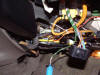
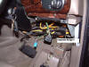
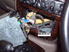
Above, the module in a vinyl box secured to the shelf to prevent it rattling.
Above it you can see the Airbag Module which contributes to the module earth.
Now test drive the car and check operation. As soon as the car reaches the
preset speed from rest the doors lock. Mine is set at 7mph - this is just above
walking speed and allows for parking manoeuvres without locking. Mine was set
for re-lock after doors open - if the car goes to 0 mph and speeds up past 7 mph
the module checks if the doors are locked. If they are not then the module sends
the signal again.
Important
The design has been well tested, but not all failure modes
can be envisaged, this is not a fail-safe design.