Automatic Headlight Extender for Ford Scorpio 95+
The Scorpio is a very well equipped car, especially in the
Ultima variant. However it was lacking in some areas in comparison to the
competition of the time. I decided to add features to the vehicle to further the
equipment level. After adding Automatic Wipers and Audible indication on Lock
and Unlock, the next project considered was an Automatic Headlight extender,
offering the function of timed courtesy operation of the headlamps.
The idea is that if required, the headlamps remain activated
when the ignition is switched off, the light from the headlamps can then be
utilized to light up the drive, or add illumination in a dark street or carpark.
After a short period of 30 seconds or so the lights switch off.
Additionally an optional auxiliary input can be utilized, this
can turn on the headlights, when the ignition is off. One use of this is
possibly in partnership with the Audible indication system (AWD), so that
headlamps are turned on when the remote keyfob is activated to open the door
locks.
Furthermore the project is designed to be relatively easy to
construct, even for someone with very little practical experience.
The system does not affect the normal use of the headlights and
is suitable for any Ford Scorpio 95+ (It may work on other models, but this has
not been evaluated). Completed units are available in addition to blank PCB’s.
Design
As already noted, the system should be reasonably straightforward to
construct and even someone with virtually no soldering experience should be able
to build the circuit up an a wet Sunday afternoon.
Secondly the system should be simple and reasonably quick to
install with minimum wiring and modifications.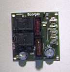
The circuit consists of two relays, 1 transistor, 2 resistors
and 4 diodes. Under normal conditions when the ignition is on and the headlamps
are on the circuit does nothing. If the headlamps are left in the 'on' position
on the selector switch and then the ignition is turned off, then the selector
turned to off, the headlamps will stay on for around 35 seconds.
Here is the techy bit for those who are interested. Relay RL1 is
turned on if the headlamps are on and RL2 contact (NC) is off as the ignition is
turned on. If the ignition is turned off the voltage at CN1 is removed as the
headlamps normally turn off with the ignition switch, however RL1 is held in for
100mS by Capacitor C2, also RL1 closes as it turns off providing voltage from
CN2, as RL1 is closed the voltage flows through RL1’s contact to CN1 and hence
holds RL1 in and provides power to the headlights.
TR1 is held on by the voltage at CN3, this is only present with ignition on.
When the ignition is turned off TR1 remains conducting as C1 supplies a base
current, C1 discharges to a point that RL1 switches off in around 35 seconds.
Once the system has timed out RL1 opens, switching off the headlamps and
completely switching off the circuit, hence no standby current is required.
Click here to download schematic in PDF
format
Construction
Note, built up units are available
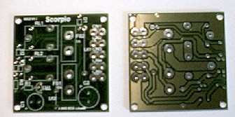
A ready made printed circuit board is available to interested
Scorpio owners. Firstly fit the resistors, diodes (noting band), links,
transistor, connectors, relays and fuse holders, then capacitors noting
polarity. The PCB is designed for easy construction, but note that through hole
plating has been used to reduce the possibility of failing joints due to
vibrations. If you solder something in the wrong position it may be difficult to
remove.
|
Quantity |
Value |
Farnell Part No |
|
2 |
470u 16V Axial Capacitor |
920-460 |
|
4 |
1N4004 Diode |
251-707 |
|
1 |
BC548C Transistor |
933-922 |
|
1 |
10K 0.25w Resistor |
509-280 |
|
1 |
1K 0.25w Resistor |
509-164 |
|
1 |
10A Automotive Fuse |
ATO |
|
1 |
1A Automotive Fuse |
ATO |
|
5 |
Push on 6.35m Faston pcb Connector |
209-284 |
|
2 |
NAIS JSM1 Automotive Relay |
910-351 |
|
2 |
Automotive Fuse Holder |
ATO 581-525 |
I used Farnell Electronics for the parts,
www.farnelll.com/uk The
approximate price at the time of writing for components, excluding PCB was
£3.50.
Installation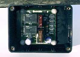
I used a small plastic case to mount the PCB into, this protects it from
moisture and enables the unit to be fitted in the engine bay. The circuit could
be fitted internally in the cabin area, but external fitting appears to require
less wiring work through glands etc. If the unit is fitted inside the cabin, no
case would be required (if the PCB could not be mechanically damaged).
The PCB has 4 M4 mounting holes, I used 4 off nylon screws and
nuts to fix the board as shown, also a grommet was fitted, shown to the right.
The area I chose for installation was near the battery as shown
in the following picture. In fact the box chosen could easily be fitted as
shown.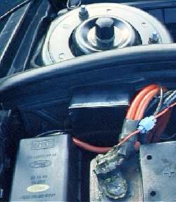
TURN IGNITION FULLY OFF!
Connections need to be made from +12V ignition; I had already
run an ignition live for the Auto Wipers, so I used this. The ignition live
supply needs only handle 1A so thin suitably rated wire can be used. This is
connected to CN3 +12V Ign on the PCB. Use suitable faston connectors to mate to
the board connectors.
The wire to the Headlight circuit must be rated to carry at
least 12A I used 2.5MM. On the left hand side in the engine bay, locate the
headlamp connector as shown.
Remove the connector from the light, using a scotch lock or
similar connector, rated for 15A, make a connection to the
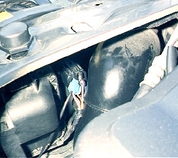 Violet/Orange
wire. This is then ran up the wing and connected to the PCB on CN1 Dipped Light.
Replace connector to light. Note you only connect to the left hand side lamp,
the existing Scorpio wiring links the left and right dipped lamps.
Violet/Orange
wire. This is then ran up the wing and connected to the PCB on CN1 Dipped Light.
Replace connector to light. Note you only connect to the left hand side lamp,
the existing Scorpio wiring links the left and right dipped lamps.
Next Connect the ground (0V, Chassis) to CN5 GND, this wire can
be thin suitably rated for 1A. If mounting the unit as shown, a connection to
the –ve side of the battery can be made.
Next remove FS2, check all your wiring, and make a connection to
the +12V Permanent supply. If again locating near the battery, a direct
connection can be made to the +12V side. Use suitably rated cable at least rated
for 12A. Take GREAT CARE when connecting to
the positive side not to short anything out. SERIOUS
BURNS CAN RESULT FROM SHORTING.
Operation & Testing
Replace FS2 back into the fuse holder. Turn the ignition on and turn the
headlamps on. Check to ensure the lights work as standard operation. Turn the
ignition off and remove the key then turn off the Headlamp selector switch. The
headlamps should remain on for 35 seconds then switch off. If you restart the
ignition before the time period has elapsed, the lights will switch off.
Remember REPLACE Battery cover!

To defeat the operation, switch off lights before switching off
ignition.
As the lights only remain on for 35 seconds after ignition is
off, no battery drain problems should occur.
Advanced
The delay before switch off was set around 35 seconds, its not known if
extending this delay may cause problems with the alarm activating on certain
models of Scorpios. However to increase or reduce the delay time, change the
value of C1.
Also provision is made for an Auxiliary input, via CN4 Aux
connection. If the ignition is off and Aux is connected to ground the lights
will turn on and stay on until the Aux signal is removed. One possible use is in
conjunction with the Audible indication system (AWD) modifications, shown on the
site. This would allow remote turning on of headlamps via the remote fob. (The
AWD program would require modifications, as is, it would just flash the
headlights 3 times).
Printed Circuit Boards, Components & Built up Units
PCB’s are available to interested Scorpio owners.
In addition a complete kit of components is available, this gets
around the minimum order quantities from many component suppliers, excluding
hardware i.e. box, wire etc is NOT included.
Also completed and tested circuits are available, but no
hardware is included.
Disclaimer and Legal
No warranties or guaranties are given; no responsibility for damage is
taken, for use of this design. It is provided purely for DIY use and you are
responsible for its use and integration. All details, circuits, etc can be
freely used and modified for non-commercial purposes.
