The Scorpio is a very well equipped car, especially in the Ultima variant.
However it is now lacking in some areas in comparison to executive cars today.
The Lock on Go system is the next in a series of add on modifications, aimed at
furthering the equipment level. Without intervention by the driver, the doors
lock automatically when reaching a preset speed. The central locking system for
the 95+ Scorpio automatically unlocks in the event of a collision and the usual
advice of the RAC, AA and the Police is that car doors should be locked during a
journey.
Note: Ready-made versions are available.Download the PDF document
here
and the items can be ordered from James Austin - prices as follows :-
The Lock on Go unit is available as follows:
Built & Tested £37.50
Blank pcb (ds, th) £12.50
Optional PC lead/converter £12.50
The Headlight Extender unit:
Built & Tested £24.00
Blank pcb £8.50
P&P is £3 for the UK and £6 for overseas. Email James for ordering info by
clicking here
Concept
The original idea was suggested by Eric R and Pete C. Steve Collister has
produced a similar addition to his very capable Global mod.
Design Brief
To produce a modification that provides automated locking of the Scorpios
central locking system upon a preset speed threshold. This provides increased
security and safety.
Technologies
Various methods are available to calculate the velocity of an object; here we
only need concern ourselves with Speed (i.e. no direction or sign of direction
is required). An electrical generator usually referred to as a “tacho” or
tachometer is one possibility; these devices provide voltage dependant on speed
of a rotating shaft. A second method is to count pulses produced in a revolution
of a rotating shaft and the technology to do this can consist of either a
switch, optical or inductive methods, or monitoring a toothed wheel connected to
the shaft where the wheel may have one or more teeth depending on the required
revolution in one rotation of the shaft. Thirdly a similar, but usually more
accurate method is to use an encoder; this is an optical device that can either
return absolute position or pulses per degree of movement. (For direction out of
phase signals are required).
Vehicle Speed Sensor (VSS)
In common with most cars today, the Ford Scorpio 95+, has a Vehicle Speed Sensor
or VSS built into its Gearbox. The VSS works on the pulse counting method and
the signal is used for the Speedometer, Climate Control, Radio AVC, Cruise
Control etc. (Interestingly some new car designs actually use one of the ABS
sensors as the VSS.)
The VSS provides a 2.2HZ per MPH square wave pulse (around 2 pulses per second
for every MPH of motion). This gives a resolution of 0.5MPH. (But due to other
factors, the Scorpios Speedometer will not be this accurate - the Speedometer
exhibits some non linear characteristics).
The VSS was chosen to provide a speed reference to the Lock on Go system, as
this method makes sense economically as no further sensor is required.
VSS V MPH

Design
Some extra features are provided, including two selectable Speed Alarms and
Re-locking after the doors open and the speed drops to 0MPH. A serial RS232 link
for programming the operational parameters and monitoring the cars speed via a
laptop or notebook PC is also provided on the board. Basic PC software is also
available but a small protocol converter is required to connect an RS232 port to
the on board connector. These features are not required if you just want a
standard pre-set system, they are only needed if you want to modify the
parameters or check the VSS speed against the Speedometer. This is useful if you
want to calibrate the system against your Speedometer.
The system consists of a ready made printed circuit board, a small
microcontroller, a relay to switch the door close signal to the central locking,
and a few other components.
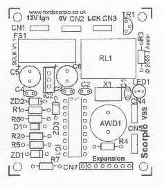
For those who are interested, here is a basic outline of the circuit. The
schematic and software for the micro controller are also included. IC2 voltage
regulator and associated components provide a 5V supply for the PIC16F628 micro
controller. Connector CN4 is connected to the Scorpios VSS signal, this is fed
via the associated resistor into Input A4, this is configured as a hardware
counter. Thus the VSS clocks an internal counter in the PIC16F628, this is then
used to calculate speed. At the desired speed Relay RL1 is activated, this
provides a +12V switching signal on CN3, this locks the central locking. Input
B0 detects if the doors are locked.
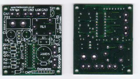
Unpopulated PCB
Construction (Optional)
If you want to construct the project yourself, blank pcb’s are also available as
well as completed and tested units.
Schematic
List of Materials
| Quantity |
Value |
Farnell Part No |
| 1 |
1N4004 |
Diode |
| 1 |
BC548C |
Transistor |
| 3 |
10K 0.25w |
Resistor |
| 1 |
120K 0.25w |
Resistor |
| 2 |
1K 0.25w |
Resistor |
| 1 |
10A Automotive Fuse |
ATO |
| 5 |
Push on 6.35m Faston pcb Connector |
209-284 |
| 1 |
NAIS JSM1 Automotive Relay |
910-351 |
| 1 |
Automotive Fuse Holder ATO |
581-525 |
| 1 |
7805 Voltage Reg |
412-594 |
| 2 |
5.1 V Zenner diodes |
|
| 1 |
15V 1W Zenner Diode |
|
| 1 |
AWD |
926-905 |
| 1 |
8 PIN SIL |
512-084 |
| 2 |
0.1uF Capacitor |
|
| 1 |
47uF 16V Capacitor Rad |
|
| 1 |
100uF 16V Capacitor Rad |
|
| 2 |
22pF Capacitor |
|
| 1 |
4mHz Resonator |
|
| 1 |
PIC16F628 |
|
| 1 |
18 Pin DIL socket |
|
| 1 |
Resistor Equipped LED 5v |
621-109 |
|
|
|
|
|
|
|
|
|
The program for the PIC micro controller is written in C, and is available
along with the Hex file here.
Construction is straightforward, the pcb has a silk screen and the components
correspond to the schematic diagram. The pcb is double side through hole plated,
so be careful not to solder components in the wrong positions, as extraction may
prove difficult.
Installation
Connections to PCB
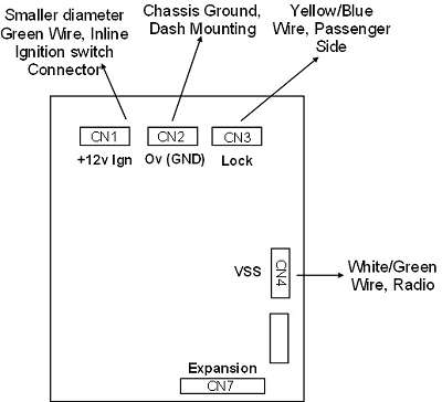
All connections to the pcb are made with faston push on connectors. Ensure the
+12V cable to CN1 and the Lock connection CN3 is suitably rated and can pass 15A
without over heating.
CN1 is the +12V supply; this can be connected to the Key On (Position 2)
ignition switch wire. The driver’s dash area that contains the Coin Box can be
dissembled by removing 4 screws. Two from the side and two from inside the Coin
Box. Locate the wires from the ignition switch and follow down to an inline
connector. The smaller diameter green wire can be connected to using a scotch
lock or similar.
CN2 is 0V (Chassis Ground), the screw that mounts the Wood Effect dash
area at the top of the drivers side lower dash area can be easily utilised as a
Ground, use a suitable circular crimp lug.
CN3 is the connection to the Central Locking Lock signal, it is easy to
locate on the front passenger side. Remove the pull off plastic cover bottom
left in the passenger well. Then remove the sound deadening felt to reveal
wiring loom. The Yellow/Blue wire is the required signal, use a scotch lock or
similar to connect to this wire. Ensure you connect to the correct wire.
CN4 is the VSS signal input. Ensure you have your radio code. Remove the
radio and locate the thin White/Green wire on one of the rear radio connectors,
use a scotch lock or similar to connect to this wire.
Expansion Connector CN7
The Expansion connector can be utilised for several purposes. Its use is
optional.
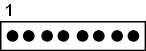
|
Pin |
Description |
| 1 |
/RESET (Active Low) |
| 2 |
ALARM OUT 20mA Max |
| 3 |
0V |
| 4 |
+5V Out |
| 5 |
+5V Out |
| 6 |
(TTL) RS232 TX |
| 7 |
(TTL) RS232 RX |
| 8 |
0V |
The common uses for this connector are, for connection to a PC for parameter
adjustment and speed reading, also connection of an external sounder or LED for
the Alarm Output, as the onboard sounder has limited output.
A ready made RS232/protocol converter lead is available if required.
For an external Speed Alarm output, connect an external LED or sounder rated for
5V; maximum 20mA, connect to Pin 2 and Pin3.
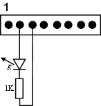
(If you write your own software for the PIC, of course you can define Pins 2, 6
& 7 as combinations of Inputs & Outputs as required).
Testing
Double check your wiring, you should have +12V with Ignition, connected on
CN1, 0V (Chassis Ground) on CN2, the Lock wire on CN3 and the VSS wire to CN4.
Additionally you may have an output device on CN7.
Warning ensure full vigilance and concentration when driving. Drive away, the
doors should lock at the pre set speed. If the doors are then unlocked and your
speed drops to 0 MPH i.e. stationary and then you drive off again, the doors may
re lock, this depends on the set-up of the unit.
Increasing speed until Speed Alarm 1 is breached and holding above this speed
for 6 consecutive seconds will cause the alarm to sound briefly, if your speed
increases past Alarm 2, again for 6 consecutive seconds the alarm will sound
again.
Important
The design has been well tested, but not all failure modes
can be envisaged, this is not a fail-safe design.
The unit is only powered when the ignition is on (if installed correctly), as
the system has direct control of the central locking system, it is not advisable
to shut the doors with the ignition on and no one is in the car. It is also
recommended that a spare vehicle key is available.
Please see disclaimer at end of this document. As this is a DIY add on unit, you
take responsibility in its use. Any potential safety issues are your
responsibility.
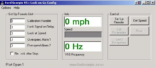
Lock on Go Configuration Software
Optional Windows software, has been written that allows certain parameters to be
set and read and for the Scorpios speed to be displayed in real time.
The software allows for calibration of the Lock on Go unit so that it is
synchronised with your speedometer. The Lock speed, Lock activation time, 2
speed alarms and relock on stop option can all be set via the software.
Also the Scorpios speed as calculated by the Lock on Go unit can be displayed,
this is useful for calibrating the unit exactly, so the Alarms activate at the
selected speeds on the speedometer.
Configuration screen shot
Lock on Go Config should work with all 32 bit Windows platforms including 98,
2000 and XP. Most USB to Serial converters and drivers should also work with the
software.
The user manual in PDF format is available
here.
The software was produced in VB6 for speed of development, and hence is not
compact; the installation files are around 2.3MB. It can be downloaded
here, alternatively it’s available on CD complete with lead.
The default values for a new unit are as follows
|
Variable |
Value |
|
Calibration variable: |
127 (2.2Hz/MPH) |
|
Lock Signal ON Delay: |
100 (1 Sec) |
|
Lock at Speed: |
5 (MPH) |
|
Alarm1: |
30 (MPH) |
|
Alarm2: |
60 (MPH) |
|
Re Lock After Stop: |
Checked |
|
|
|
(Advanced- For those who are interested and study the PIC’s code, you will
see a “back door” development route, for a terminal program such as
Hyperterminal. The settings are 9600, No Parity 1 Stop. Hold the “1” key down on
the keyboard when powering up the unit to log in, followed by “T”. Also a
“hidden” setting for lock speed is available remember your sending characters if
you try to set this, so the character code will be the value).
Lock on Go Configuration PC Software Users license
J.Austin End User License Agreement
By installing and using the SOFTWARE, you agree to be bound by the terms of this
LICENSE. If you do not agree to the terms of this LICENSE, do not install or use
the SOFTWARE.
This SOFTWARE is provided as is. No warranty, expressed or implied, with regard
to the software. Under no circumstances shall J.Austin or www.fordscorpio.co.uk,
or agents of, be liable for any incidental or consequential damages or losses.
The use of this software and any related hardware is your responsibility, DIY
use.
This software or any hardware and related designs may not be used for any
commercial purposes.
Disclaimer and Legal
If you use any design, software or hardware relating to this design, in doing so
you are acknowledging your agreement with the following.
No warranties or guaranties are given; no responsibility for damage is taken,
for use of this design. No responsibility is taken for direct, consequential or
incidental damages or losses. It is provided purely for DIY use and you are
responsible for its use and integration. All details, source code etc can be
freely used and modified for non-commercial purposes. Use of the Configuration
PC software is at your risk, no warranties are given.

