Indicator Flash-on-Lock

Introduction
On the Ford Scorpio various central locking configurations are available
dependent on country of sale. Most UK variants will either not flash on lock or
flash a short delay after deadlocking, if ultrasonic sensors are fitted. In
many cases an FMD can reprogram them using WDS for a charge, but some early
models cannot be programmed in this way. Additionally no audible feedback is
available.
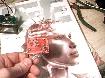
For this reason a small circuit was developed to emulate the flashing
indicators on other manufacturers' models. The modification is small and simple
to install. It provides an on off single flash with a duration of around 0.5
seconds when the doors are locked, provided the ignition is off. Only one flash
is provided and no second confirmation of double locking, as this is usually
provided. A sounder can also be fitted to provide an audible indication of
locking.
Design
The design is simple and,
unlike some of the other
projects I developed for the Scorpio,
does not have a microcontroller. In
fact it has only a few components. The design reflects a low cost approach with
such things as ATO fuse holders and fuses replaced with 20mm fuses, with direct
wiring rather than terminals.
With reference to the schematic diagram
(Acrobat required), when the ignition is off and the doors are locked a 12V
level is applied to CN1, as Capacitor C2 is discharged previous to this point by
Resistor R2, a current flows through C2 and the coil of relay RL1, causing RL1
to close introducing a supply to the indicators and the sounder (AWD) via the
associated blocking diodes, this current rapidly drops as C2 charges up, at a
point of around 0.5 seconds after the locking signal appearing, RL1 opens as
insufficient current flows to develop its holding voltage. If the ignition were
to on, RL1 would not close when the doors locked, as C2 would be previously
charged via R1 and D2.
R2 rapidly
discharges C2 when the lock signal or ignition signal is removed, hence
“resetting” the circuit for the next lock operation.
Installation
The eight wires are shown in the table, YELLOW & BLUE are optional and are for a
sounder (12Vdc max 300mA). Splice and extend the wires as required, either with
butt splices, scotch locks or solder and tape method. (Noting that Scotch Lock
type connectors must be sized correctly for the wire diameter and fitted
correctly). Insulate all connections including the sounder wires if not used.
Above table shows
the wires coming from the Flash on Lock unit.
RED
is Permanent +12V from the battery and this supply can be found on the rear of
the DLC connector. The driver’s dash area that contains the Coin Box can be
dissembled by removing 4 screws. Two from the side and two from inside the Coin
Box. This wire should be Orange and on pin 16 of the connector (DLC-OBD2). Or
connect to a suitable +12V Permanent supply point, if one is already available.
BLACK
is 0V (Chassis Ground), the screw that mounts the Wood Effect dash area at the
top of the drivers side lower dash area can be easily utilised as a Ground, use
a suitable circular crimp lug. Or connect to a suitable GND if one is already
available.
GREEN
is the connection to the Central Locking Lock signal; it is easy to locate on
the front passenger side. Remove the pull off plastic cover bottom left in the
passenger well. Then remove the sound deadening felt to reveal wiring loom.
The Yellow/Blue wire is the required signal, use a scotch lock or similar to
connect to this wire. Ensure you connect to the correct
wire. (This wire is also used on the
Lock on Go unit)
BROWN
is the Ignition +12V supply; this can be connected to the Key On (Position 2)
ignition switch wire. The driver’s dash area that contains the Coin Box can be
dissembled by removing 4 screws. Two from the side and two from inside the Coin
Box. Locate the wires from the ignition switch and follow down to an inline
connector. The smaller diameter green wire can be connected to using a scotch
lock or similar. This signal stops the system flashing the indicators when the
ignition is on and the doors are locked.
Or connect to a suitable Ignition +12V if one is already available.
PINK
This connection can be made in the
engine bay at the Left Hand Indicator; it’s the Blue/Orange wire coming from the
indicator.
VIOLET
This connection can
be made in the engine bay at the Right Hand Indicator, it’s the Blue wire coming
from the indicator.
When you have completed and checked the installation, you are ready to test the
system. Simply lock the doors with ignition off and the indicators and sounder
(when fitted) should operate.
This device can be purchased from James Austin
M.I.E.E.
Mail him on:
James
Austin
Before use please read the notice below:
If you use
this design, in doing so you are acknowledging your agreement with the
following.
No warranties
or guaranties are given; no responsibility for damage is taken, for use of this
design. No responsibility is taken for direct, consequential or incidental
damages or losses. It is provided purely for diy use and you are responsible for
its use and integration. All details can be freely used and modified for
non-commercial purposes.
This is not a
fail-safe design; incorrect installation or a failure may cause Indicator lamp(s)
to operate.
