
![]()
![]()
![]()
![]()
|
|
|
|
|
|
|
Last update: 08/03/2005 |
|
|
|
|
|
|
|
|
|
|
|
Adding the Under-Door Lighting Option to a Scorpio
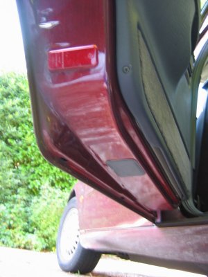
Introduction Later Scorpio Ultima owners have often aired their annoyance on discovering that under-door lighting was withdrawn in 1997, making their fully-loaded car short of an option. However, it is not impossible to retro-fit the feature to any car, and, depending on what is still left in the car, it may be quite easy. Disclaimer This item describes the way I installed under-door lighting. It does not use the standard Ford connections at all points, so results in non-standard wiring. I believe it to be safe, but I am not a qualified car electrician! Of course all wiring work in a car carries some risk of damage, and an incorrect connection can blow an expensive component, or cause a fire. You must take full responsibility for any such work you may do on your own car. Getting the hole and the lights to go in it The first thing to check is whether the car has the under-door hole for fitting the light. Cars which have the hole but no lights are fitted with a blanking plate, as shown in the illustration here.
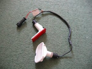
If there is no hole it is always possible to cut one. A template for a proper Ford hole is provided here, but if cheaper non-Ford lights are to be used a different hole may be needed, or even several if a few hi-brightness LEDs are considered! Note that the Ford light units are expensive, and you need four for a car. I understand that Granadas, even Escorts may have similar light units, and a trip to the scrappy, or an examination of Ebay may be called for! Template - TEMPLATE.BMP Download this bitmap and use Ms Paint to print the file. The printed template will then be the correct size. A picture of the Ford pair of lights for a door and their harness is below.
Under-door light harness
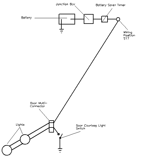
Providing power Even if there is a hole in the door base, it is unlikely that the wiring inside the door to connect the lights up will exist. So, as well as the light harness, ancillary wiring is needed. The plug which conects to the light unit socket will be useful. Also, the light cables pass through a multi-connector at the door hinge, and the pins and sockets for the door lights will not be in the connector if the car did not have the light option originally. If a multi-connector or two can be found, pin/socket pairs can be salvaged to replace the missing ones. A simple schematic of the original under-door lighting circuit is shown here. Power is taken from a central +12v point controlled by a battery-saving timer, and then passed to each door light. It then returns to ground via the door-open switch, so the lights come on when the door is open.
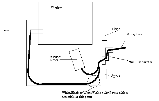
Original Schematic In-door only wiring If all doors and boot are open on a car with footwell lights as well, the total drain will be the best part of 100W. So you can see why a saver circuit is a good idea. Unfortunately, the saver-controlled wiring position S17 is believed to lie behind the dashboard, and gaining access to it is not easy. So this piece describes a simpler way to connect the lights, using the internal door wiring +12v line to the door lock. This keeps most of the work inside the door, and saves threading long lengths of cable through the car. The down-side is that there is no battery saver circuit, so the doors should not be left open with the lights on for ages!. \par \par The internal door wiring looks like the drawing below. There is only one appropriate wire to power the lights in each door, which is contained in the loom at the point specified. It is usually easy to separate the wires at this point, and I think that all cars will have this particular wire. It is coloured White/Violet in the front doors, where it comes from pin 16 of the multi-connector, while in the rear doors it is coloured White/Black, and comes from pin 6. It is +12V at all times that the door is unlocked, and connected to earth when it is locked. In each door I tested the wire with a multi-meter and a dressmakers pin to be sure I had the right one before connecting.
Scorpio door wiring The revised schematic for connection is fairly simple, and is shown below. A Scotchlock connector takes the +12v from the door Power cable and passes it to the light harness. The return cable from the light harness goes through the multi-connector, and terminates in the courtesy switch in the car body, just as the standard Ford design does.
New Connection Schematic One complexity is that this Power cable is connected to earth when the car is locked. So the entire light system out to the courtesy switch is grounded at this time. Unfortunately, other circuits also monitor the state of the courtesy switch - if it is grounded the door must be open. So a direct connection to this Power cable makes the car think the door is open when it is locked, and the internal lights will be turned on. We can prevent this by putting a diode in the line which will stop this reverse current. Shown on the circuit is a 1N4001 diode (obtainable at Maplins, P/N 1141234). The diode must be connected into the circuit the right way around - the diagram below shows how to tell which this is.
Diode Diagram
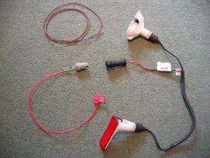
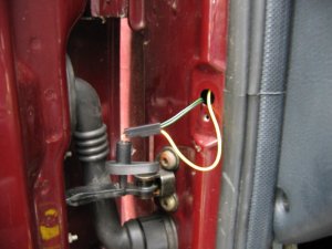
Doing the Work Needed: 4 sets of under-door lights Holes to put them in (see Template above) 4 Scotch-locks for 5A wire 4 diodes - 1N4001 will do A cross-head screwdriver and a flat one with a long shaft About 5 yards of thin 2A wire. A large knife 1 foot long metal tube about 3/16" in diameter (see Step 3 below!) Wiring ties if you cut any Soldering iron, or some method of connecting and insulating wires. Nice to have: The full wiring harness, including multi-connector plug and socket A multi-meter pins and sockets for the multi-connector Process Step 1 - I made up the connections. If I had the full harness I might have looked for power from a different point inside the car body. Point S17, if I could find it, or the footwell lights if I had them were possibilities. If I had the pins/sockets for the multi-connector I would have broken the wires at this point and installed the extra connections. I decided to make up a harness plug from filler, but I could have bought an original plug, or cut the Ford one off and soldered extension wires directly on.\par \par For my door-connector loom the following cables were extended from the end of the light harness plug: - a cable approx 1ft, ending in a Scotchlock, for connecting to the in-door power cable +12V.\par - a thin cable approx 3 ft, for connecting through the multi-connector to the door-open switch. (But not attached yet - the cable will need to be threaded through some narrow spaces first!). Note the (hard to see!) diode attached to the plug in the picture below.
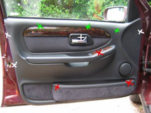
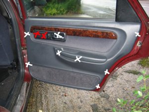
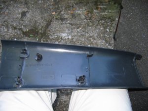
Made-up plug and harness picture Step 2 - I removed the internal door panel. A detailed write-up on how to do this is described at http://www.fordscorpio.co.uk/doorlockrep.htm but a picture is included below showing the location of the screws. There are 6 in the front and 10 in the rear, some hidden under the arm-rest or behind the window switch panel but once undone the panel lifts up and away from the door easily - the easiest of all car door panels I have ever removed! In the pictures the white crosses are visible screws, the red ones are hidden behind a cover, while the green ones are push studs connecting behind the door.
Front Door Panel
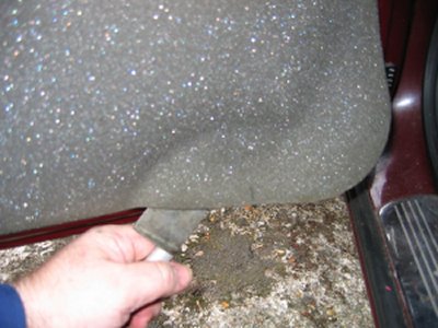
Rear Door Panel Behind the panel is sound proofing sponge foam. I unsealed this at the bottom of the door, using the knife to cut through the mastic and peel the foam plastic away. If the weather is hot it comes off easily. It will immediately join again if you push it back.
Sound proofing separation At this point I could install the light units. There is a little steel spring clip which holds them onto the door skin. It's also a good idea to find and test the power cable which will be used - I used a dressmakers pin to connect to it.
Light unit installed
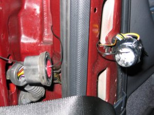
Testing the Power wire Step 3 - The hardest job is to connect the earth lead from the light harness through the multi-connector to the courtesy switch. Since I did not have the extra pin/socket for the multi-connector I passed the cable directly through the holes in the multi-connector where the pin/socket is missing. Cheeky, but it works, and can easily be upgraded later if necessary. The only difficulty is that you need thin wire \endash standard 5A is too thick. The actual drain when running is 1A, so 2A wire should be fine.
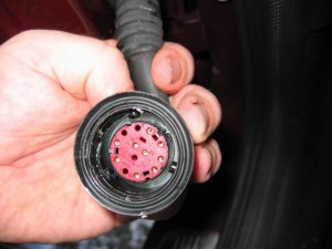
Multi-connector
Multi connector open
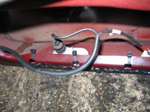
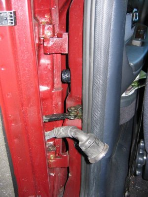
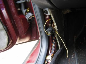
Missing holes After undoing the multi-connector, (it turns easily), I prised off the rubber hose which carries the wires through into the door at the connector, and pulled it out where it connects into the door. Then I pushed the metal tube up through it, so I could easily thread the earth wire through. Did you wonder what it was needed for? It's easiest to begin in the middle, by pushing the wire through one of the spare multi-connector holes. Then I passed it through the metal tube in the rubber hose, and removed the tube. Finally, I connected the earth wire to my diode and plug.
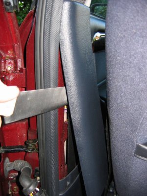
Releasing rear trim
Rear trim internal connectors Next I went inside the car, and removed the trim behind the multi-connector base. For the rear doors multi-connector it can be prised out with the knife. The base of the multi-connector is held with a lip which can be bent up, allowing the multi-connector to be rotated and removed. I passed the cable through the hole in the side of the car, then the hole in the multi-connector base which corresponded to the hole I had used in the other half. Once done I replaced the multi-connector base.
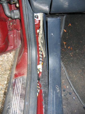
Wire through rear connector
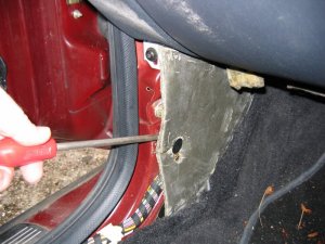
Wire through front connector The front of the car was more tricky. The plastic panels by the sills have to be undone before levering off the trim in the footwell. Then I was faced with some sound proofing, held down with a plastic plug. After levering the plug off, I could just get my hand behind the sound proofing to touch the multi-connector. To release the metal lip which retains it, I had to cut a flap in the sound proofing and use a long screwdriver to lever the lip up, working blind. Then I had just enough room to remove the multi-connector base. The cable could then be passed through, and the base replaced, as with the rear example. It is probably possible to pass a wire through the multi-conector base without removing it, by using a small mirror to view the holes, and a stiff wire to push the other wires aside.
Undoing front trim
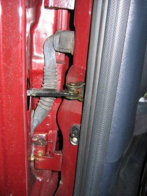
Levering plug out Once through the multi-connector, the earth wire connects to the door open switch which is about 6" away. There will be a wire already in place there \endash I fixed it to this and then connected the other end of the cable to my diode and plug in the door. Allow enough slack in the car body side to open the multi-connector in the future.
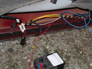
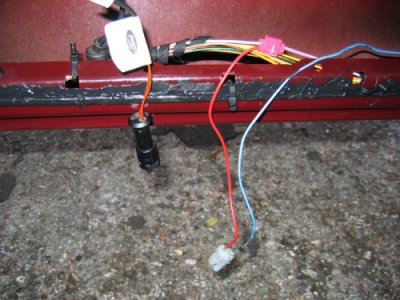
Earth Connection Step 4 - Finally, I connected the +12V power line. This was easy - I just undid the door wiring loom clip at the base of the door at the hinge side, and separated out the power cable. White/Violet in the front door, White/Black in the rear. I scotch-locked the +12V power cable to this and connected the other end to my plug. When I joined the plug and socket, the lights lit up so long as the door was open and unlocked.
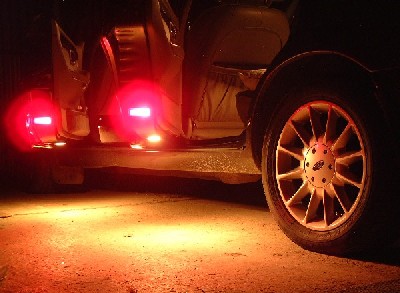
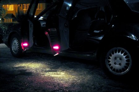
Scotchlock to power cable Step 5 - I tested the lights, paying particular attention to whether the door lock system worked, and whether all lights, including the roof ones, worked when needed and turned off when not needed. I re-assembled all the trim and reconnected the multi-connector. I checked that everything was properly electrically insulated, not under strain, and clipped down (Scorpios don't have rattles!). Then I tested it once more, and replaced the sound proofing and door panel. One 'feature' of this power connection to the door lights is that they can be turned on and off remotely by operating the door locks while the doors are open. It' s a good way to save power if the door has to be left open for a long time but it's also great fun, and runs the risk of flattening the battery while showing off your handiwork to your friends!
Testing the lights Chris B
|
|
|
|
|
Copyright © 2003 www.fordscorpio.co.uk |
|
|
|

