|


|
|
Replacing Blown LEDs - the Scorpio Trip Computer Switch.
article by Chris BaxterSeveral of the
Scorpio’s dashboard lights are prone to fail and then prove difficult to
replace. The Computer Switch is a good example of this, since it uses a less
common type of Light Emitting Diode (LED) to provide the green light behind the
buttons. These fail quite often, and are soldered into a printed circuit board
(PCB), making them hard to change. If each of your Computer Switch buttons do
not light up green when the ignition is turned on, one (or more!) of these LEDs
has failed.
A new Computer Switch will cost £20 or more, though they are quite easy to
install. If, however, you do not want to spend this sort of money, you can just
buy some new LEDs, unsolder the failed one(s) and replace them. This will cost
about 50p per LED (maximum of three).
Points to make before we start:
 |
Don’t try this if you don’t know what a soldering
iron is – you need a bit of experience to unsolder and resolder components. Not
a lot, but you might want to practice on something cheaper first! |
|
|
You may have trouble matching the precise green of
existing LEDs. The LEDs referenced here are easy to obtain, but a bit yellower
than Fords. You may wish to change all three to match, or go for a different
colour like red. |
Parts needed:
|
|
Replacement LEDs - I used MAPLINS green 3mm 12v
hi-brightness LED (catalogue Number CJ69A). Any similar LED will work, but
Maplins (http://www.maplin.co.uk) is a common high-street supplier. You must
get 12v ones – 2v ones will just blow. |
|
|
Jewellers screwdriver with about 1/8" wide blade
|
|
|
Soldering equipment |
Follow these step by step instructions
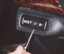
Step 1
Lever the Trip Computer switch out of the fascia with the small screwdriver -
try to get the blade between the switch body and the fascia so as not to cause
any scratching. (picture right). Alternatively you can remove the screw holding
the lower panel, one to the left of the Steering Wheel, two inside the coin
cubby and two on the side where the door slams. Pulling the panel down will
reveal the back of the switch and avoid any chance of scratching the surround.
|
|
|
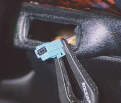 |
Step 2
Unplug the switch and tie the loom so it does not fall back into the hole.
(picture left)
If it does then you will have to remove the lower panel after all. |
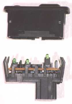
Step 3
Use the jewellers screwdriver to lever open the four clips which hold the switch
together without breaking them. Hold it button side down, and pull the two
halves apart. Do this over somewhere where you can look on the ground for any
springs you may drop! (picture right).
Note that there are two very small springs and they WILL fall out although
reassembly is quite easy when you have found them. |
|
|
|
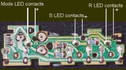
Step 4
The PCB just unclips and pulls out. Picture left shows the back of it, with
arrows indicating the LED solder points. |
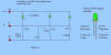
Unlike an incandescent light, LEDs are polarised, and must be inserted the
correct way round. Observe the polarity of the LEDs on the PCB before you remove
them. Internally they will look like the drawing next to the schematic in the
below (click it for a better view). The Anode is the name of the connection
which must go to the + 12v part of the circuit (marked LED on the schematic and
your PCB). It will be the longer of the two wires coming out of the LED you have
bought. The internal drawing will help if you have cut the wires on the diode
already!
|
Step 5
Use a soldering iron to loosen the solder connections holding in one of the dead
LEDs, and remove it. If you leave the other LEDs in you can always use them to
check the correct polarity if you forget! Either clear the solder hole
completely with the iron, or use a very small drill to remove the solder in the
hole, otherwise you might push the PCB track off the PCB when inserting the new
LED (I did – it’s delicate!). |
Click for full size image |
| |
Step 6
Bend the wires of a new LED to resemble the one you have removed, insert it, and
re-solder this in, clipping the excess wire afterwards. If you have more than
one to do, it’s a good idea to plug the PCB into its housing and attach it to
the loom to check that you have the LED in correctly after each one. If you
don’t, you may have to reverse three rather than one! |
Step 7
Now is a good time to clean the metal clicking contacts with a bit of Meths –
the buttons can sometimes be a bit unreliable. |
|
| |
Step 8
Replace PCB, reassemble switch, and reconnect. Check the operation of the lights
and buttons, then go down to the pub with the £20 you have just saved! |
|
|
| |
|
|
|

