|


|
|
INSTALLATION OF 8 SENSOR
PARKING RADAR
This write-up applies to the
Cosworth saloon, facelift model 1998, and an eight sensor parking system for
front and rear bumpers. Although this is specific to the facelift model
fitting it to others will be very similar.
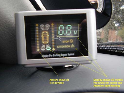
Both sets of sensors (front and back) will pick up objects from approx
1.5 metres away and the unit will start to bleep. The bleep speed
increases as you approach the obstacle until, when
about 0.8 metres away the "attention" light comes
on and at about 0.5 metres away the "stop" light
comes on and the bleeps are fast. The distance display, in tenths of a
metre, also flash and the display indicates which direction you are
going in. (see above) By experimentation I have found that when the display
reaches zero distance, the car is actually about 25 - 30 cm away from
the obstruction, so giving a modest safety margin.
|
1.
1.
Installing rear
sensors
a.
Positioning
sensors
Remove interior panels from the
boot and boot lid, to gain access to wiring for offside light cluster, fuel
cut-off switch, and reversing lights in boot lid. Also remove carpet and
underlay from boot floor.
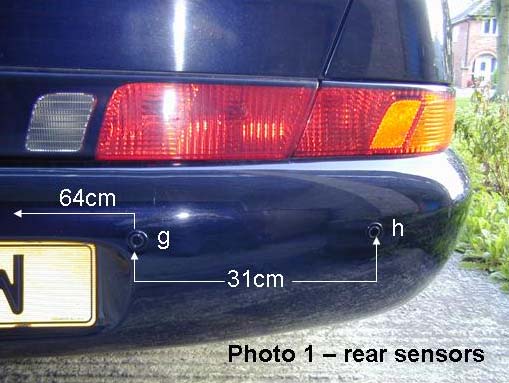
It was not
necessary to remove the bumper. The positions are as shown in Photo 1. I
chose positions that would give a horizontal rearward line for all 4
sensors, but the outer pair were positioned to cover a slightly outward
angled beam.
For the positions shown there were no
obstructions on the inside of the bumper. I used masking tape in the
vicinity of each location before marking the sensor positions. A ⅛th pilot
hole was drilled first, to act as a guide for the hole cutter provided as
part of the kit. When using the hole cutter only minimal pressure was
applied in order to avoid overheating the composite material of the bumper
or running on into any obstruction further behind.
|
 |
b. Wiring
Using a length of plastic coated curtain wire, or similar, with each
sensor’s screened cable attached in turn, the cables were fed in the
correct order across the car [In my case, e, f, g, h, going from near to
off side] inside the double skin of the bumper to an oval hole on the
inside at the offside end. Once all wires were through, the sensors were
pressed into the holes until flush with the bumper and the 4 cables
covered with black insulating tape for protection.
|
 |
2. Installing front sensors
a. Removal of front bumper
The front bumper must be removed so that positioning the sensors avoids
all strengthening webs, headlamp washers, wiring and other obstructions.
The instructions given on the Ford Scorpio website did not apply to this
car. There are no clips to be rotated 90º on each side and there are
four holding bolts at the front, not two. There is no need to remove the
washer bottle.
The following items secure the front bumper to the car: Remove them in
this order, supporting the bumper at the middle and each side. Removal
is a 2-person operation.
Remove the headlamp side covers, 3 torx headed screws.
Disconnect the cable multiplugs to the front sidelights and indicators
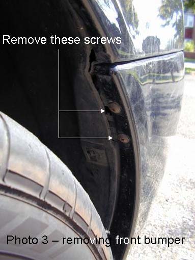
and, if fitted, the fog lights.Remove two plastic screws each side of
the front wings.
|
 |
|
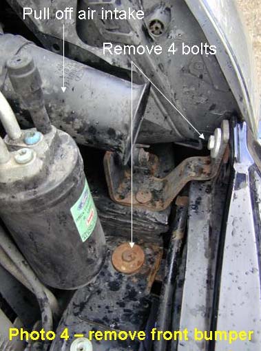
Pull off the air intake
pipe extension and remove the four bolts holding the front bumper to the
car – two each side. |
 |
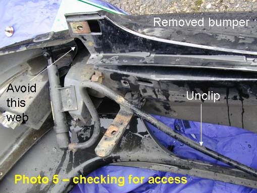
| Disconnect the pipe clipped across the rear
of the bumper moulding, which connects the nearside headlamp washer with
the washer bottle. Note the internal web on the bumper |
 |
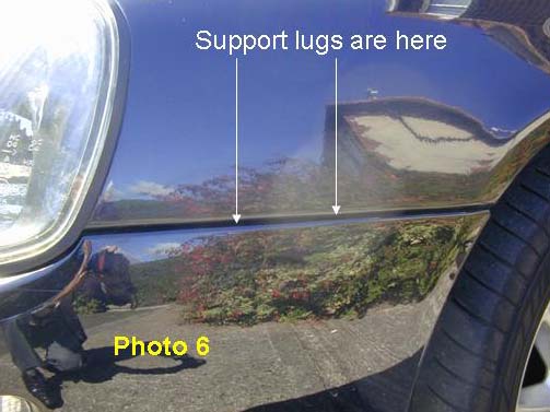
| The sides of the bumper are held to the
front wings by two plastic mouldings (lugs) on each of the wings, which
correspond to slots in the bumper sides. To disengage these care is
required to avoid snapping the lugs. This is done by easing the bumper
sides outwards and upwards slightly.
Once the sides of the bumper are clear of the wings, slide the bumper
forwards away from the car and put it on the ground. I put it on an old
blanket to protect the paintwork |
 |
b. Positioning sensors
It is now possible to check that the proposed positions of the sensors
will not foul anything behind the front skin.
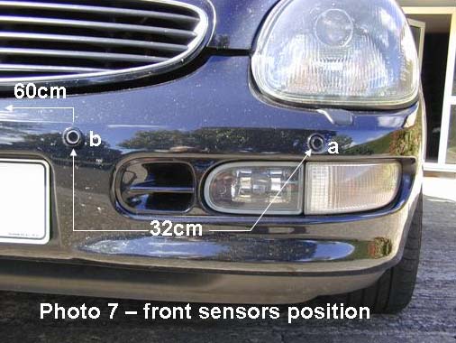
Mark up the hole positions as described for the rear bumper, but see
Photo 7 for dimensions, and drill the pilot holes. Use the supplied hole
cutter as described above. |
 |
Wiring
Fit the sensors in the correct order across the car [in my case, a, b,
c, d going from near to off side]. I used plastic covered curtain wire
to guide each screened cable inside the double skin to the offside of
the bumper where they exited roughly in the position of the offside
headlight side cover. Once all through, the 4 cables were covered with
black insulating tape for protection over most of their length. The
bumper was then re-attached to the car and secured with the bolts only
at the stage and the loom wiring re-connected.
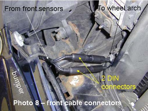
Because the front bumper may have to be removed from the car for other
repair or maintenance reasons in the future, I decided to fit connectors
to the sensor wires. I used two 4-pin mini DIN plugs and sockets, one
for each pair of screened cables (8-pin DIN were not available).
One pair of cables from two sensors was soldered to a plug and the other
pair to a socket, in order to ensure correct re-connecting during any
future operations.
|
 |
|
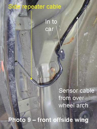
Next step is to remove
the side plastic trim in the driver’s foot well between the door and the
pedals. Then jack up the front of the car and remove the offside road
wheel, in order to remove the wheel arch lining. I then fed the sensor
cables through into the wheel arch via an existing hole above and
forward of the washer bottle filler, over the top of the suspension
[there is a convenient lip or channel to lay the cables in] and down
towards the rear of the wheel arch. I secured the cables with plastic
ties or duct tape where convenient.
There is an existing
cable from the direction repeater light on the wing that goes into the
car interior via a rubber grommet. I fed the sensor cables through the
same grommet and into the car [driver’s foot well].
|
 |
| The wheel arch lining
was then replaced and the trailing edge of both sides of the bumper
refastened using new rivets as required. The road wheel was re-fitted
and the car lowered to the ground.
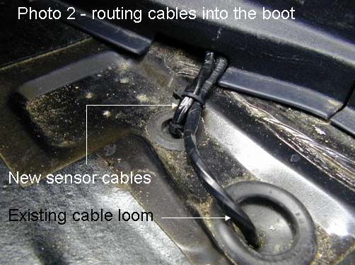
The sensor cables were then routed to the boot under the carpet side
trims, under the rear seat back and in to the boot, clipped to the
existing wiring loom as required all the way back to the rear light
cluster. Plastic trims were replaced afterwards.
|
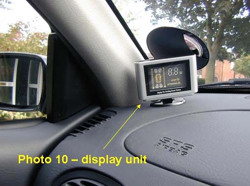
3. Installing display unit
a. PositioningThe position I chose is shown in Photo 10, as this
enabled me to see through the dipping door mirror and watch the display
at the same time, whilst not interfering with forward vision.
b. Wiring
The single wire from the display unit was concealed between the
dashboard and the door closing trim, down into the passenger foot well
[you will have to remove the trim panel between the door and the foot
well side], and then under the carpet side trim to the rear seat, across
under the rear seat squab and into the boot alongside the front sensor
cables.
|
 |
4. Installing the controller
a. Connecting wires to car loom
You now have all the sensor and display unit cables adjacent to the
offside rear light cluster. The Controller requires connecting to an
“ignition on” power supply, negative [I used a bolt on the rear light
cluster] the brake light [this powers the front sensors] and the
reversing light. The cable to the reversing light was led under the rear
parcel shelf and alongside the wiring loom into the boot lid.
I did not cut any existing wires, but pared back the insulation for
about 10mm and soldered the Controller cables to the existing car
cables, insulating the joints afterwards. This will avoid problems with
the sensitive wiring system of this car. To avoid disturbing the loom
and its protective wrapping:-
• the power supply was connected to purple with orange at the fuel
cut-off switch [this is 12v live, but only when the engine is running].
• the brake cable was connected to purple with black near to the rear
light cluster.
• the reverse cable was connected to purple with black near to the
reverse light cluster in the boot lid.
Naturally, it would be advisable on your car to double check the colour
coding and that you have 12v before cutting into any insulation!
|
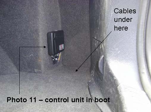
| b. Positioning
The Controller was positioned as shown in Photo 11, and a short slit was
made in the carpet side panel for the cables.
The base of this panel below the Controller is about 20mm above the boot
floor, so is a convenient place for any over length cables to be coiled
up. All that remained was to test the system, to ensure that near side
sensors lit up the near side display and that there were no blind spots
in the sensors’ coverage [there weren’t!], and replace the boot
panelling and floor carpet.
|
 |
5. Conclusion
I
am very pleased with the result. The installation looks “original” to the
car and the sensors pick up anything within about 1.8 metres, including high
kerbs. It makes parking in a tight space much easier than before,
particularly as the shape of the Scorpio makes it difficult to judge precise
positioning.
I have
found the unit really excellent. Reverse "sees" further than forward for
some reason and already I have avoided a prang when reversing slowly out of
a blind parking bay and a car shot across my stern from my blind side, but
the sensor went into alarm mode so I instinctively hit the brakes. So, I
would recommend this kit - especially as the Scorpio shape makes it
difficult to precisely judge distances. If front sensors were more sensitive
and if the display was easier to see in daylight, I would award 10 out of
ten. With those two qualifications, I give it 8 out of ten.
Name: 8 Sensor Parking
Radar with Smart
Display
Price: £54.99 + £7.50 p&p and insurance
Seller: gtonline, Belshill UK (email:
tgonline@blueyonder.co.uk)
Neil D
Wallace; August 2004
|
|
